Supercharge Your Innovation With Domain-Expert AI Agents!

Wind driven generator

A wind power generation equipment and wind power technology, which is applied in the directions of wind turbine components, wind turbines, and wind turbine combinations, etc., can solve the problem that the shaft cannot be coupled, the power transmission of wind blades cannot be carried out, and the orientation of the nacelle of the wind tower cannot be self-adjusted, etc. question

Inactive Publication Date: 2011-01-26
GREAT PROMISE INT
View PDF0 Cites 21 Cited by
  • Summary
  • Abstract
  • Description
  • Claims
  • Application Information

AI Technical Summary

Problems solved by technology

[0005] The first technical problem: the rotating shaft of the wind blade must rotate with the change of the wind direction, which cannot be coupled with the rotating shaft of the fixed transmission device fixed in the wind power tower, so that the power of the wind blade cannot be transmitted to the power generation equipment
[0006] The second technical problem: large wind power towers are as high as 100 meters, how to transmit the power of the wind blades from the top of the tower to the bottom of the tower is also a problem that needs to be considered
[0007] The third technical problem: the orientation of the nacelle of the wind power tower cannot be self-adjusted, and an additional control program needs to be set up to operate the motor to adjust the direction of the nacelle through the wind direction data provided by other devices, so that the wind blades are facing the wind direction

Method used


Image

  • Wind driven generator
  • Wind driven generator
  • Wind driven generator

Examples


Embodiment Construction

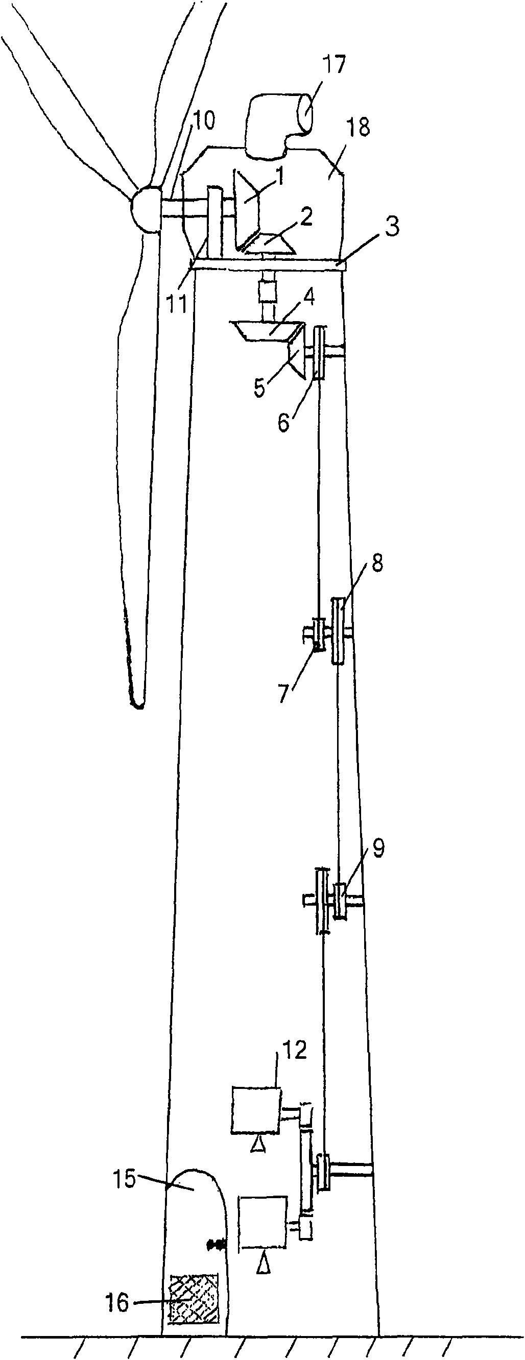
[0021] figure 1 The horizontal wind power generation equipment according to the present invention is shown, wherein a wind power tower is erected on the ground, a nacelle that can rotate with the wind direction is installed on the top of the wind power tower, and wind blades are installed at one end of the wind power tower. From figure 1 It can be clearly seen that the power generation equipment 12 is arranged at the bottom of the wind power tower.

[0022] The wind blade is supported on a support member 11 in the nacelle through a rotating rod 10 . The supporting part 11 is fixedly installed on the rotating disk 3 . The rotating disk 3 can rotate relative to the wind power tower. The first helical gear 1 is fixed at the other end of the rotating rod 10, and the first helical gear 1 rotates in the vertical plane driven by the fan blades. The first helical gear 1 meshes with the second helical gear 2 so that the second helical gear 2 rotates in a horizontal plane. Through ...


PUM


Abstract

The invention relates to horizontal type wind driven generating equipment. A generator is arranged on the bottom of a tower, and the rotation of fan blades is transferred through a pair of engaged helical gears, wherein the rotating circle center of the helical gears rotating in a horizontal plane is arranged in the rotating circle center of an engine room, so that the direction of the complete set of equipment can be adjusted in correspondence to wind direction, and the rotation is transferred to the generator through multiple sections of pulley blocks. The bottom and the top of the wind power tower are respectively provided with a one-way vent port, so that natural cooling in the wind power tower is realized. The invention relates to a horizontal type wind driven generator with double fan blades. The generator greatly increases generating efficiency. A wind direction tracker comprises a conducting pin fixed with a wind vane, two conducting plates and an insulating strip clamped between the conducting plates. When the wind vane rotates, and the conducting needle rotates correspondingly so as to be in electric contact with the conducting plates, and an external control circuit is engaged to drive a motor to regulate a rotating disk until the conducting needle is in contact with the insulating strip once again.

Description

technical field [0001] The invention relates to the field of wind power generation equipment, in particular to wind power generation equipment with wind blades arranged horizontally. Background technique [0002] As a kind of green energy, wind energy is inexhaustible and inexhaustible. Many countries in the world have already begun to use wind power generation technology to provide electricity. The wind wheel of traditional wind power generation equipment rotates roughly 8-20 circles per minute under the drive of wind force. This kind of wind power generation equipment also needs the cooperation of the wind direction tracking device to generate wind power, but the wind direction tracking device is expensive and easy to damage, and it is difficult to adapt to the wind with fast changing wind direction or the wind with unstable wind direction. Existing wind power generation equipment is generally a horizontal axis type or a vertical axis type. Horizontal axis wind power gen...

Claims


Application Information

Patent Timeline
IPC IPC(8): F03D9/00F03D1/00F03D1/06F03D7/04F03D11/00
CPCY02E10/723Y02E10/722Y02E10/721Y02E10/72
Inventor 周建煌
Owner GREAT PROMISE INT
Features
  • R&D
  • Intellectual Property
  • Life Sciences
  • Materials
  • Tech Scout
  • Unparalleled Data Quality
  • Higher Quality Content
  • 60% Fewer Hallucinations
Learn More