Brake system for a vehicle

A braking system and service braking technology, applied in the direction of brakes, vehicle components, brake transmission devices, etc., can solve the problems of high cost and expensive manufacturing of the braking system, and achieve the effect of enhancing the parking brake pressure

Active Publication Date: 2011-01-26
ZF CV SYST EURO BV
View PDF1 Cites 16 Cited by
  • Summary
  • Abstract
  • Description
  • Claims
  • Application Information

AI Technical Summary

Problems solved by technology

The overload protection valve 26 makes the braking system expensive to manufacture
Furthermore, the overload protection valve 26 requires a certain assembly outlay, so that the overload protection function of the brake or the brake cylinder 8 of the braking system 2 according to the prior art results in higher the cost of

Method used


Image

  • Brake system for a vehicle
  • Brake system for a vehicle
  • Brake system for a vehicle

Examples


Embodiment Construction

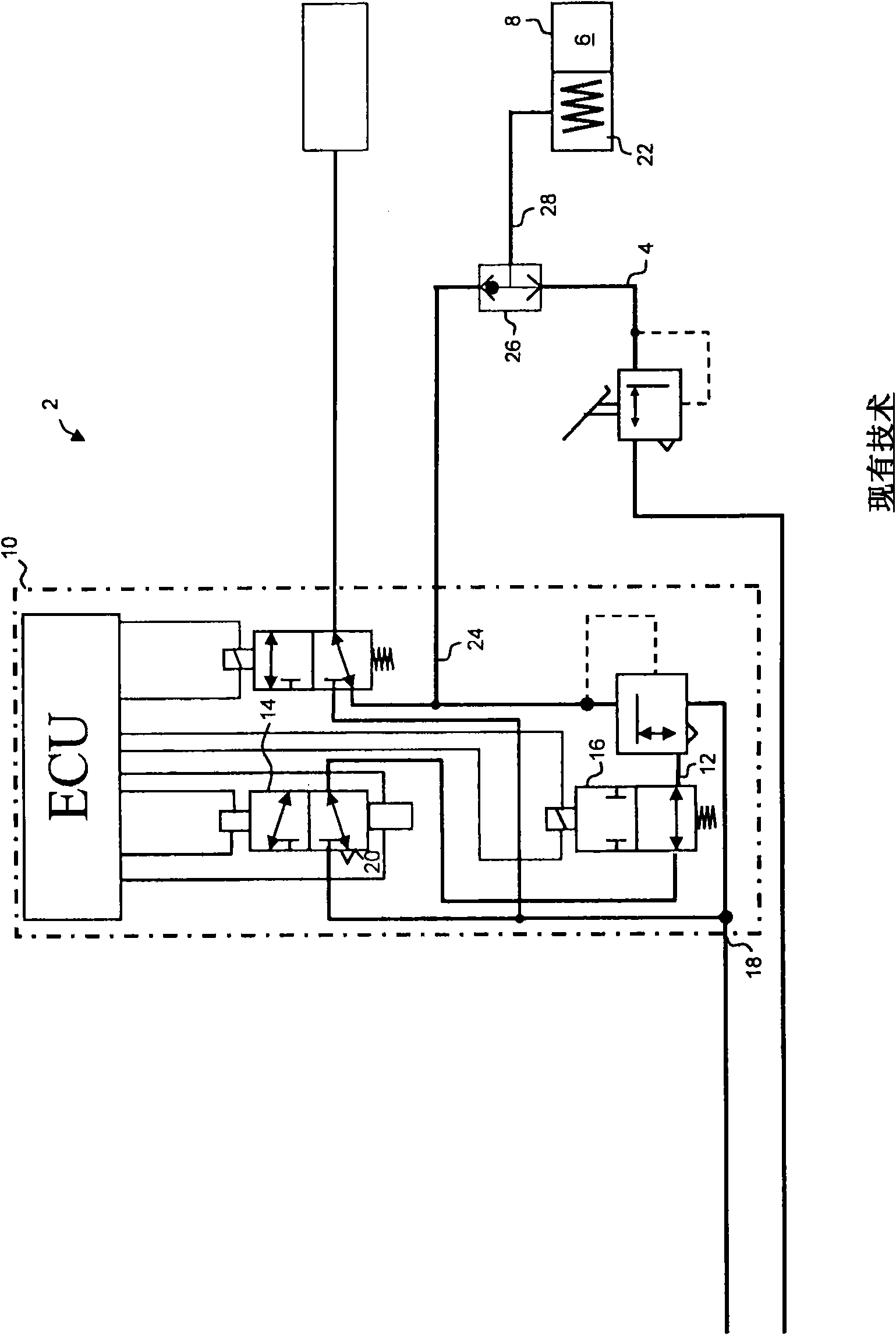
[0021] figure 1 It has been introduced in the preamble of the description in order to illustrate the important features of the prior art.

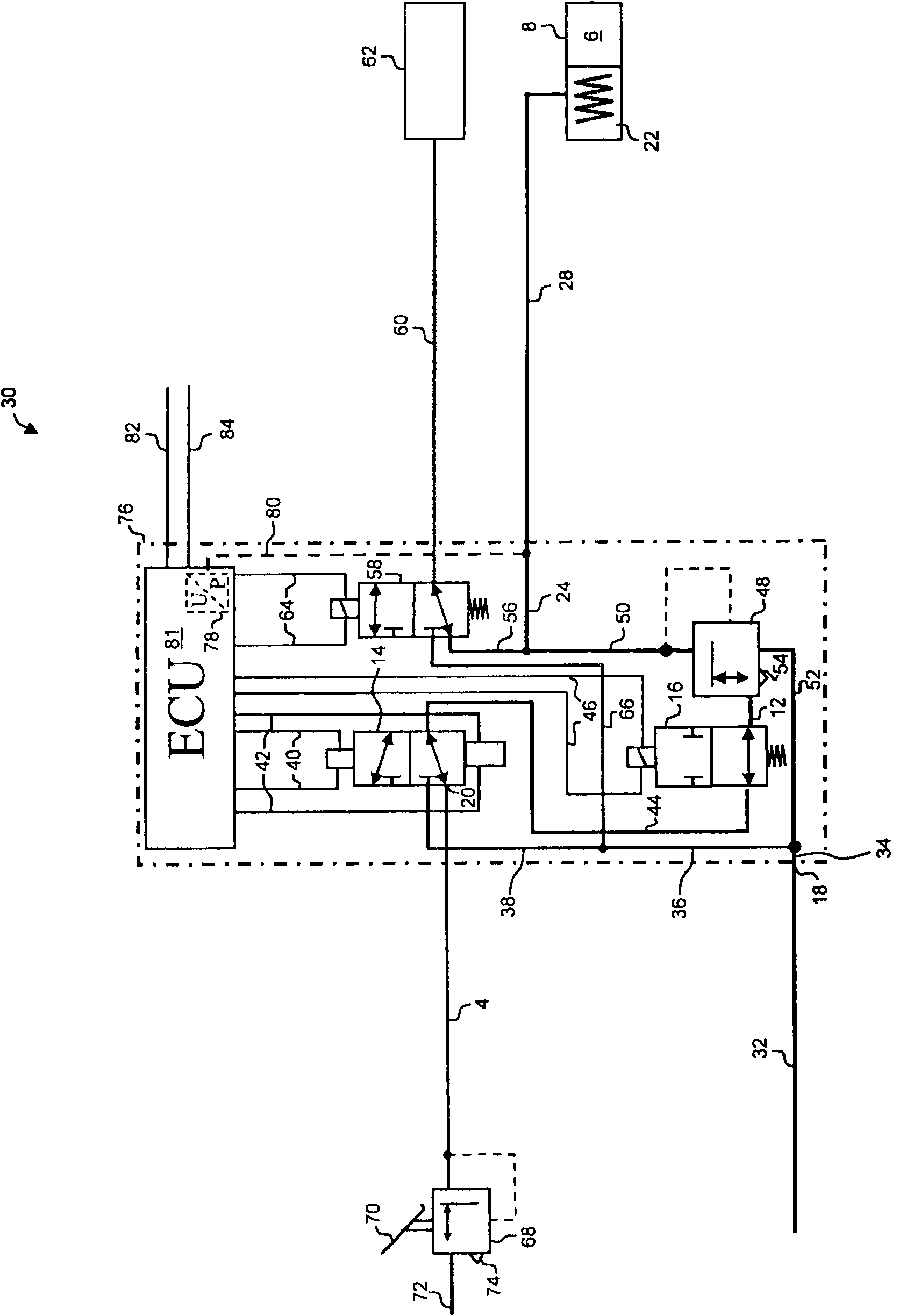
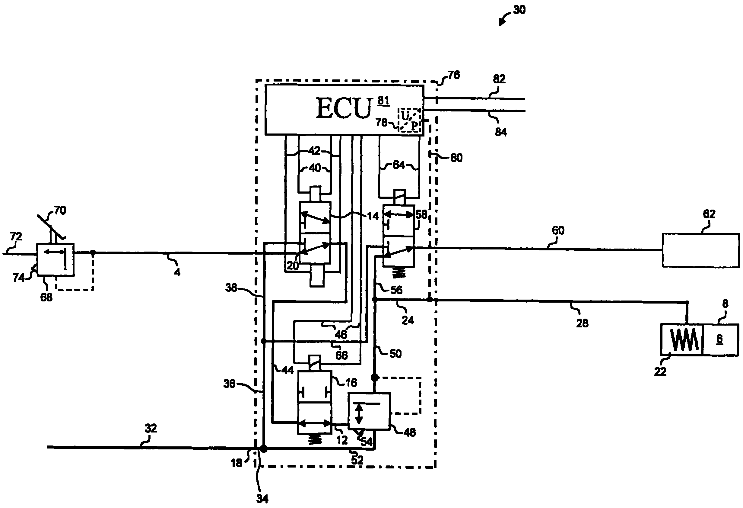
[0022] figure 2 Shown is a braking system 30 according to the invention which is partly compatible with the figure 1 The braking system 2 of the prior art is the same. In this respect, the same reference numerals designate the same components and refer to the corresponding above-described embodiments.

[0023] In the case of the brake system 30 , compressed air with a reserve air pressure emerges from a compressed air reserve container (not shown) via a compressed air line 32 to the ventilation inlet 18 . Compressed air lines 34 , 36 and 38 lead compressed air to the first solenoid valve 14 , which is implemented as a bistable valve. The bistable valve 14 is switchable in two switching states. To this end, the magnetic coil is controlled via electrical lines 40 and 42 to switch between said states. The bistable valve 14 remains in i...


PUM


Abstract

The invention relates to a pneumatically operated brake system (30) for a vehicle. Said brake system (30) has a first compressed air line (4), in which compressed air having a controllable service brake pressure can be provided. Membrane parts (6) of brake cylinders (8) can be ventilated by means of said service brake pressure for a service brake function of said vehicle. Said brake system (30) further has a parking brake device (76) comprising a second compressed air line (12). Compressed air can be provided in said second compressed air line (12) by means of said parking brake device (76) at a parking brake pressure that can be activated in an electro-pneumatic manner. Spring brake parts (22) of the brake cylinders (8) can be ventilated by compressed air having said service brake pressure in order to provide a parking brake function of said vehicle. The parking brake device (76) further has a ventilation inlet (18), by way of which the second compressed air line (12) can be ventilated in order to increase the parking brake pressure using compressed air. Furthermore, said parking brake device (76) has a first ventilation outlet (20), by way of which said second compressed air line (12) can be ventilated in order to reduce said parking brake pressure. According to the invention, the second compressed air line (12) can be pneumatically connected to the first compressed air line(4) via the first ventilation outlet (20).

Description

technical field [0001] The invention relates to a brake system for vehicles operated by means of compressed air, as is known, for example, from DE 103 36 611 A1. This brake system has a service brake function and a parking brake function. With the service brake function, the diaphragm part of the brake cylinder can be ventilated with compressed air at an adjustable service brake pressure. With the parking brake function, it is possible to ventilate the spring accumulator part of a brake cylinder, in particular a combination including a diaphragm part, with compressed air having an electro-pneumatically adjustable parking brake pressure type spring accumulator / diaphragm brake cylinder. Background technique [0002] Furthermore, the known brake system has an overload protection function for the brake cylinder. This should refer to figure 1 The prior art is shown in detail. [0003] figure 1 Components of the brake system 2 are shown with a first compressed air line 4 in ...

Claims


Application Information

Patent Timeline
Patent Type & Authority Applications(China)
IPC IPC(8): B60T13/38B60T13/68
CPCB60T13/385B60T13/683
Inventor 乌韦·本施伯恩德-约阿希姆·基尔维尔弗里德·门泽尔哈特穆特·罗森达尔
Owner ZF CV SYST EURO BV
Why Eureka
Try Eureka