Sub-Assembly for an Electromechanical Brake Actuator

a technology of brake actuator and sub-assembly, which is applied in the direction of braking system, braking system, electric vehicle, etc., can solve problems such as the failure of the operation of the gear uni

Active Publication Date: 2012-12-27
LUCAS AUTOMOTIVE GMBH
View PDF5 Cites 46 Cited by
  • Summary
  • Abstract
  • Description
  • Claims
  • Application Information

AI Technical Summary

Benefits of technology

[0007]A feature of the present invention is to provide an improved construction for an electromechanical brake actuator.

Problems solved by technology

For example, already an external damage to the housing may result in the operational failure of the gear unit if it is supported directly on the housing.

Method used


Image

  • Sub-Assembly for an Electromechanical Brake Actuator
  • Sub-Assembly for an Electromechanical Brake Actuator
  • Sub-Assembly for an Electromechanical Brake Actuator

Examples


Embodiment Construction

[0035]An embodiment of an assembly of an electromechanical brake actuator for an electrically operated parking brake is explained below. Corresponding elements in the Figures are given the same reference numerals. Terms such as “at the upper side” and “at the lower side” refer to the orientation of the assembly illustrated in the Figures. Of course, the electromechanical brake actuator may be orientated as desired (for example laid laterally) during installation.

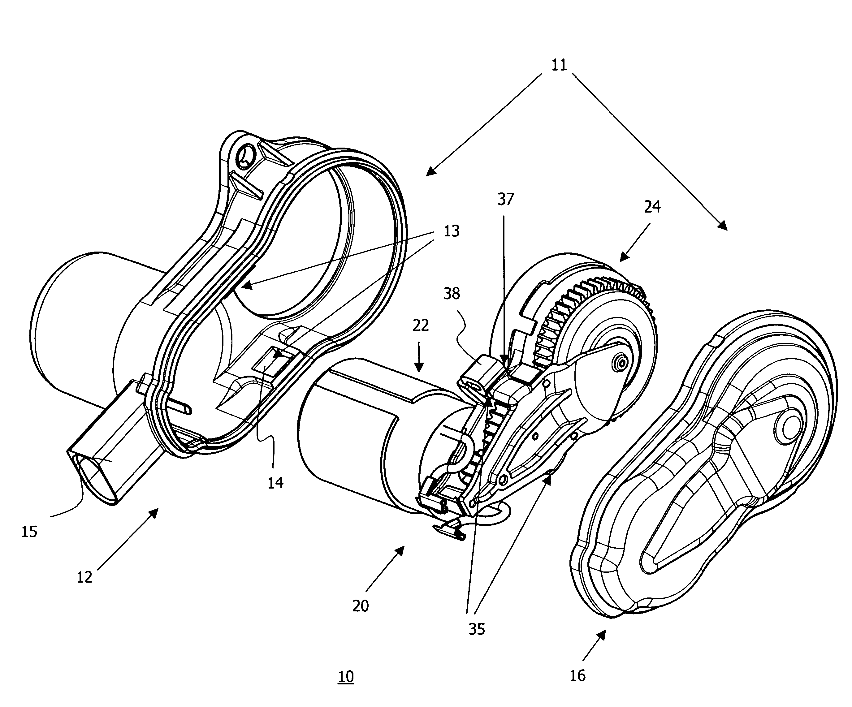
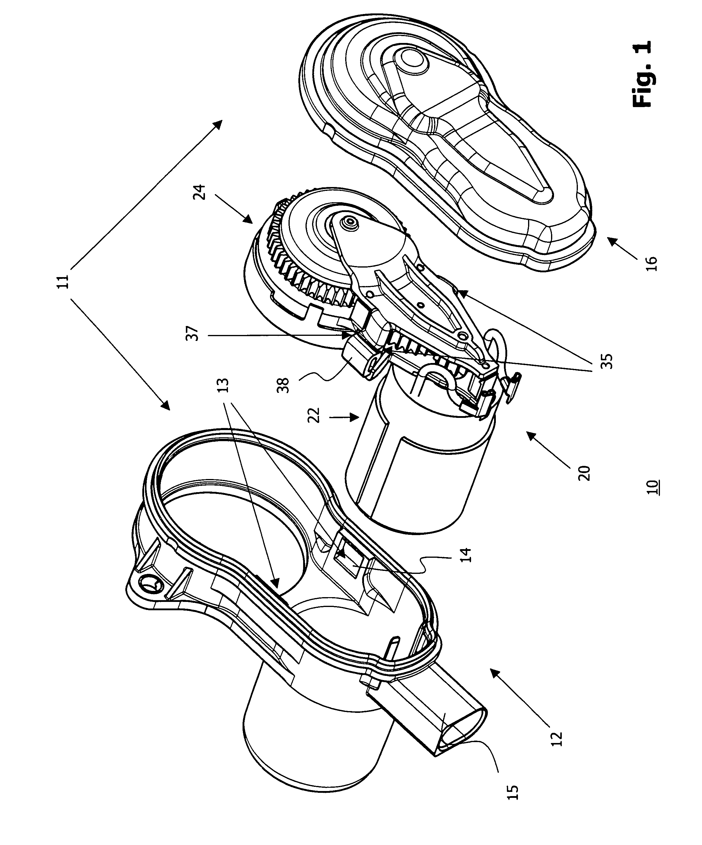
[0036]FIG. 1 is a perspective view of essential components of an assembly 10 of an electromechanical brake actuator. The assembly 10 comprises a housing 11 having a housing lower portion 12 and a housing upper portion 16 and a subassembly 20, which substantially comprises a drive device 22 and a gear device 24. Furthermore, the subassembly 20 has a first mounting device 35 which comprises two carriers 37 (only one carrier can be seen in FIG. 1 owing to the perspective view) which are each provided with a damping element 38 a...


PUM


Abstract

The invention relates to a subassembly for a brake actuator which is provided for an electromechanically operated parking brake. The subassembly comprises a drive device and gear device for generating and transmitting a torque to a brake device and a fixing element which secures the arrangement of the gear device relative to the drive device, an internal-toothed wheel of the gear device being integrated in the fixing element.

Description

CROSS-REFERENCE TO RELATED APPLICATIONS[0001]This application is a national stage of International Application No. PCT / EP2010 / 004544 filed Jul. 23, 2010, the disclosures of which are incorporated herein by reference in entirety, and which claimed priority to German Patent Application No. DE 10 2009 060 201.1 filed Dec. 23, 2009, the disclosures of which are incorporated herein by reference in entirety.BACKGROUND OF THE INVENTION[0002]The present invention relates to the field of motor vehicle brakes. More precisely, the invention relates to an improved construction of a subassembly of a brake actuator which is provided for an electromechanically operated parking brake or an electromechanically operated service brake.[0003]Electrically operated parking brakes are used increasingly often in motor vehicles. They have the advantage that they can be controlled with modern on-board electronic systems, thereby opening up new possibilities for the use of parking brakes in a motor vehicle. F...

Claims


Application Information

Patent Timeline
Patent Type & Authority Applications(United States)
IPC IPC(8): B60T13/74F16D65/16
CPCF16D65/0006F16D65/18F16D2125/50F16D2125/48F16D2121/24F16D2121/26F16H1/46
Inventor GIERING, WILFRIED
Owner LUCAS AUTOMOTIVE GMBH
Why Eureka
Try Eureka