Turnover device

A technology of turning over equipment and main frame, which is applied in ship design, conveyor objects, ship parts, etc. It can solve the problems of rotary knuckle overload, frequent faults, oversize, etc., to simplify the functional structure, improve safety, and improve space the effect of using

Active Publication Date: 2012-12-05
HYUNDAI HEAVY IND CO LTD
View PDF5 Cites 0 Cited by
  • Summary
  • Abstract
  • Description
  • Claims
  • Application Information

AI Technical Summary

Problems solved by technology

In the above turning equipment, the upper main beam has a cantilever structure with respect to the swivel joint, so the swivel joint may be overloaded, causing frequent failures and shortening the life expectancy of the equipment
Furthermore, the main beam for placing the heavy material has an excessive length, and the turning process is carried out by the main beam combined with the heavy material, so the turning device is undesirably oversized, and requires an excessively large area for the execution of the flip work

Method used


Image

  • Turnover device
  • Turnover device
  • Turnover device

Examples


Embodiment Construction

[0035] Hereinafter, a preferred embodiment of the present invention will be described in detail with reference to the accompanying drawings.

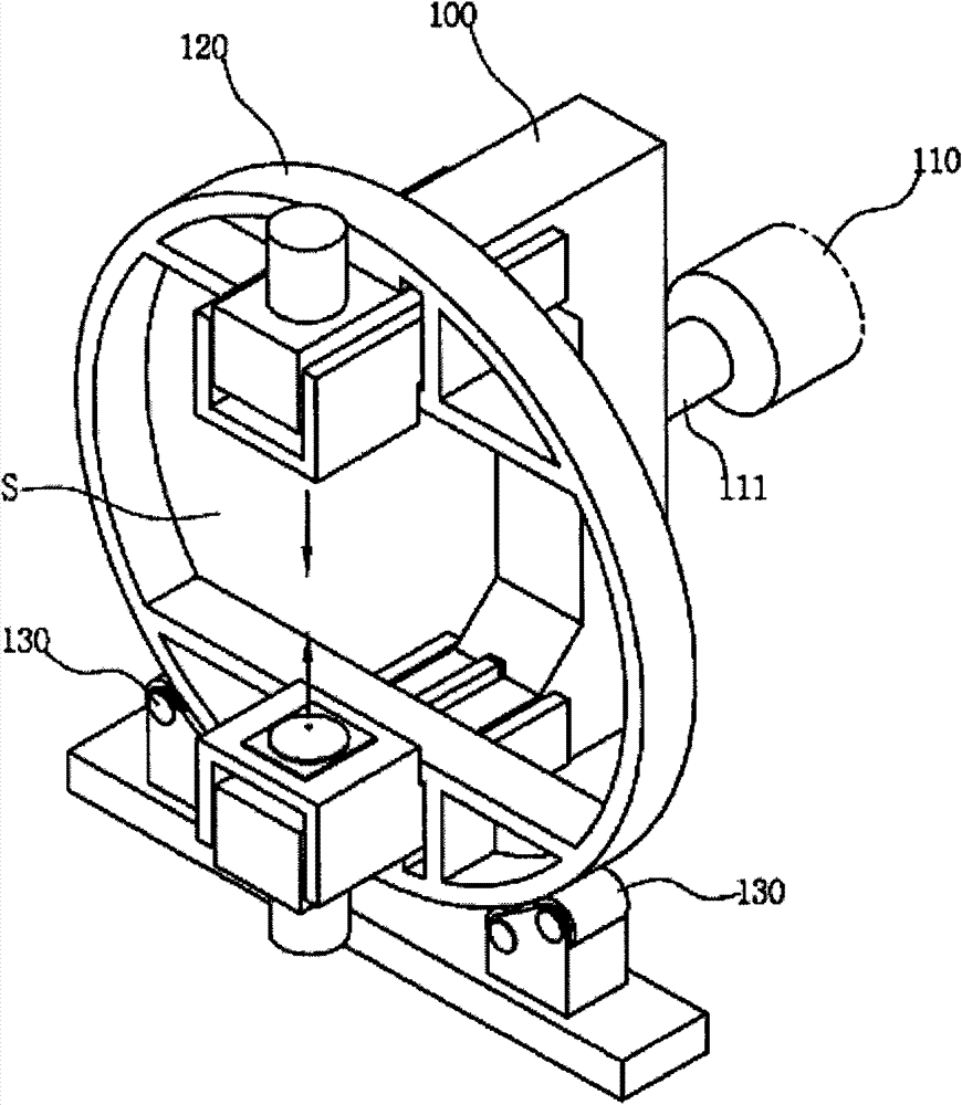
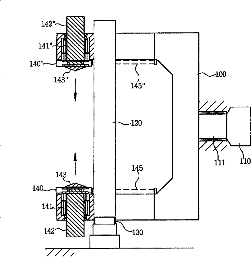
[0036] figure 2 is a perspective view of a turning device according to a preferred embodiment of the present invention. image 3 is a side view of a turning device according to a preferred embodiment of the present invention. Figure 4 is a perspective view of a turning device according to the invention illustrating the operation of the rack. Figure 5 yes Figure 4 An enlarged view of an important part of . Figure 6 is a side sectional view illustrating the operation of the movable sub-frame provided in the main frame according to the present invention. Such as Figure 2 to Figure 6 As shown, the turning device according to this preferred embodiment of the present invention includes a main frame 100 , a turning driving unit 110 and supporting rollers 130 .

[0037] The main chassis 100 has a U-shaped structure opened in one dir...


PUM


Abstract

The present invention relates to a turnover device. The objective of the present invention is to improve spatial utilization as well as simplify the structure of a frame by enabling the insertion of a large structure without the opening and closing of the frame during insertion and turning processes for the initial installation of the large structure with a hollow part such as a propeller and to implement a structurally stable rotation of the frame during the turning process. The present invention comprises the frame, a turning drive, a round reinforcement frame, and support rollers. A space into which the large structure with the hollow part is inserted is formed on the central part of the frame, a pair of fixing cones facing the hollow part of the large structure inserted into the space are placed on the upper and the lower part of the space, and the frame comprises a chucking cylinder which is connected to and moves each fixing cone. The turning drive connects through a rotary shaft to one side of the frame and turns the frame. The round reinforcement frame is integrated with the frame. The rotary shaft turned by the turning drive is spatially positioned at the center of the round reinforcement frame. The support rollers are positioned under the reinforcement frame in order to contact the outer circumference of the reinforcement frame.

Description

technical field [0001] In general, the present invention relates to an inverting apparatus, and more particularly, to an inverting apparatus for inverting a large-sized device having a hollow portion along a central axis, such as a marine propeller. Background technique [0002] In the manufacture of propellers of large size, after casting the propeller, it is necessary to turn the propeller about 6 to 8 times, so that it enters several machining steps (shearing riser (riser cropping), forming for fixing Eyebolt holes for thrusters, cutting punch lower surface, cutting punch upper surface, drilling, milling blade front surface, milling blade rear surface, grinding said blade front surface, grinding said blade rear surface and inspection / teleport the thruster). [0003] In the related art, the process of turning over the thruster is carried out as follows: ① locking the eyebolt for turning over the thruster in the threaded hole formed in the central part of the side surface...

Claims


Application Information

Patent Timeline
Patent Type & Authority Patents(China)
IPC IPC(8): B63B17/00
CPCB63B17/00B65G47/252B63B9/00B63B71/00
Inventor 辛尚龙卢泰飏廉斗植李知炯李润植金志瑥金钟佑田炳振
Owner HYUNDAI HEAVY IND CO LTD
Why Eureka
Try Eureka