Spraying robot

A spraying robot and nozzle technology, applied in the field of robots, can solve the problems of inconvenient, difficult control of spraying distance and thickness, and achieve the effect of precise control of spraying thickness

Inactive Publication Date: 2011-02-02
刘宝龙
View PDF6 Cites 6 Cited by
  • Summary
  • Abstract
  • Description
  • Claims
  • Application Information

AI Technical Summary

Problems solved by technology

[0003] At present, with the continuous development of the die-casting industry, there are higher requirements for the efficiency and quality of the production of die-casting parts. During the die-casting process, it is necessary to spray a release agent on the surface of the m

Method used


Image

  • Spraying robot
  • Spraying robot
  • Spraying robot

Examples


Embodiment Construction

[0012] The present invention will be further described below in conjunction with the accompanying drawings and embodiments.

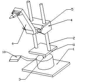
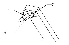
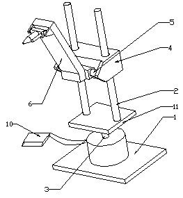
[0013] Such as figure 1 , 2 As shown, a spraying robot includes a base 1, a column 2, a base rotating shaft 3, a sliding seat 4, an arm rotating shaft 5, an arm 6, a nozzle rotating shaft 7, a nozzle 8, a rangefinder 9, a control system and a column base 11, The base 1 is provided with a base motor, the base motor is connected with the base rotating shaft 3, the base rotating shaft 3 is fixed with a column seat 11, and two columns 2 are fixed on the column seat 11, and two columns 2 are provided with a The sliding seat 4 is provided with an arm rotating shaft 5, and the arm 6 is connected to the sliding seat 4 through the arm rotating shaft 5, the nozzle rotating shaft 7 is fixed on the front end of the arm 6, and the nozzle 8 is connected to the arm 6 through the nozzle rotating shaft 7. The distance meter 9 is fixed on one side of the nozzle 8; the ...


PUM


Abstract

The invention relates to a spraying robot, which comprises a base, stand columns, a base rotating shaft, a slide seat, an arm rotating shaft, an arm, a nozzle rotating shaft, a nozzle, a diastimeter, a control system and a stand column seat, wherein a base motor is arranged on the base, and the base motor is connected with the base rotating shaft; the stand column seat is fixed on the base rotating shaft, and two stand columns are fixed on the stand column seat; the two stand columns are provided with the slide seat which can slide along the stand columns, the slide seat is provided with the arm rotating shaft, and the arm is connected to the slide seat by the arm rotating shaft; the nozzle shaft is fixed on the front end of the arm, the nozzle is connected to the arm by the nozzle rotating shaft, and the diastimeter is fixed at one side of the nozzle; the slide seat, the arm and the nozzle are respectively connected with respective corresponding motors, and the diastimeter and the motors are respectively connected with the control system. The diastimeter transmits the measured distance value to the control system, and then the control system controls the accurate moving and rotation of the slide seat or rotating shafts by controlling the slide seat and the motors of the rotating shafts so as to accurately control the distance of the nozzle and the coating thickness in the process of spraying.

Description

[0001] technical field [0002] The invention relates to a robot, in particular to a spraying robot. Background technique [0003] At present, with the continuous development of the die-casting industry, there are higher requirements for the efficiency and quality of the production of die-casting parts. During the die-casting process, it is necessary to spray a release agent on the surface of the mold. At present, the spraying of the release agent is mainly done by manual and mechanical spraying. However, mechanical spraying requires expensive spraying equipment, and the spraying distance and thickness are not easy to control during spraying, which is very inconvenient. Contents of the invention [0004] The object of the present invention is to overcome above-mentioned deficiencies in prior art, provide a kind of simple in structure, cheap, and can control the distance of nozzle and spraying thickness, very convenient spraying robot. [0005] To achieve the above object,...

Claims


Application Information

Patent Timeline
IPC IPC(8): B05B13/04
Inventor 刘宝龙王海磊徐德钦于复生
Owner 刘宝龙
Why Eureka
Try Eureka