Combination material deflector and door seal for a material spreader

a technology of material spreader and deflector, which is applied in the direction of lighting and heating equipment, roads, roads, etc., can solve the problems of material clinging to the discharge system of the spreader, material clinging to the material deflector may also fall off during traveling, and adverse effects

Active Publication Date: 2014-10-28
KUHN NORTH AMERICA
View PDF12 Cites 6 Cited by
  • Summary
  • Abstract
  • Description
  • Claims
  • Application Information

AI Technical Summary

Benefits of technology

[0007]Accordingly, one aspect of the present invention is to provide accurate control of the distance traveled and the spread pattern of the material discharged by the spreader apparatus.
[0008]Another aspect of the present invention is to prevent or reduce the unwanted discharge of material from the spreading apparatus, especially during traveling of the spreader apparatus to the desired location.
[0009]One non-limiting embodiment of the present invention can provide a container for the material, a discharge unit which discharges the material, a deflector door disposed on a discharge port of the discharge unit, a positioning device which positions the deflector door and a controller configured to control the deflector door so that the deflector door is positioned at a position of a user's choosing between a first closed position and a second open position. The deflector door substantially covers the discharge port when the deflector door is in the first position such that the material is substantially prevented from exiting through the discharge port.
[0016]In another non-limiting embodiment, the deflector door completely covers the discharge port when the deflector door is in the first position such that the material is prevented from exiting through the discharge port.
[0017]A method of spreading material includes discharging material from a spreading apparatus, deflecting the discharged material with a deflector door such that a distance that the material is discharged is based on a position of the deflector door, and covering a discharge port of the spreader apparatus with the deflector door such that material is substantially prevented from exiting through the discharge port.

Problems solved by technology

However, the spreader apparatus typically has to travel to and from the location where the material is spread.
In some conventional apparatuses, it is possible that the material clinging to the discharge system on the spreader may fall off the machine during traveling.
In addition, material clinging to the material deflector may also fall off during traveling.
There may be adverse consequences if the material in the discharge system of the spreader apparatus were to exit the spreader apparatus into the surrounding environment, such as a roadway, when the spreading apparatus is not in operation.

Method used


Image

  • Combination material deflector and door seal for a material spreader
  • Combination material deflector and door seal for a material spreader
  • Combination material deflector and door seal for a material spreader

Examples


Embodiment Construction

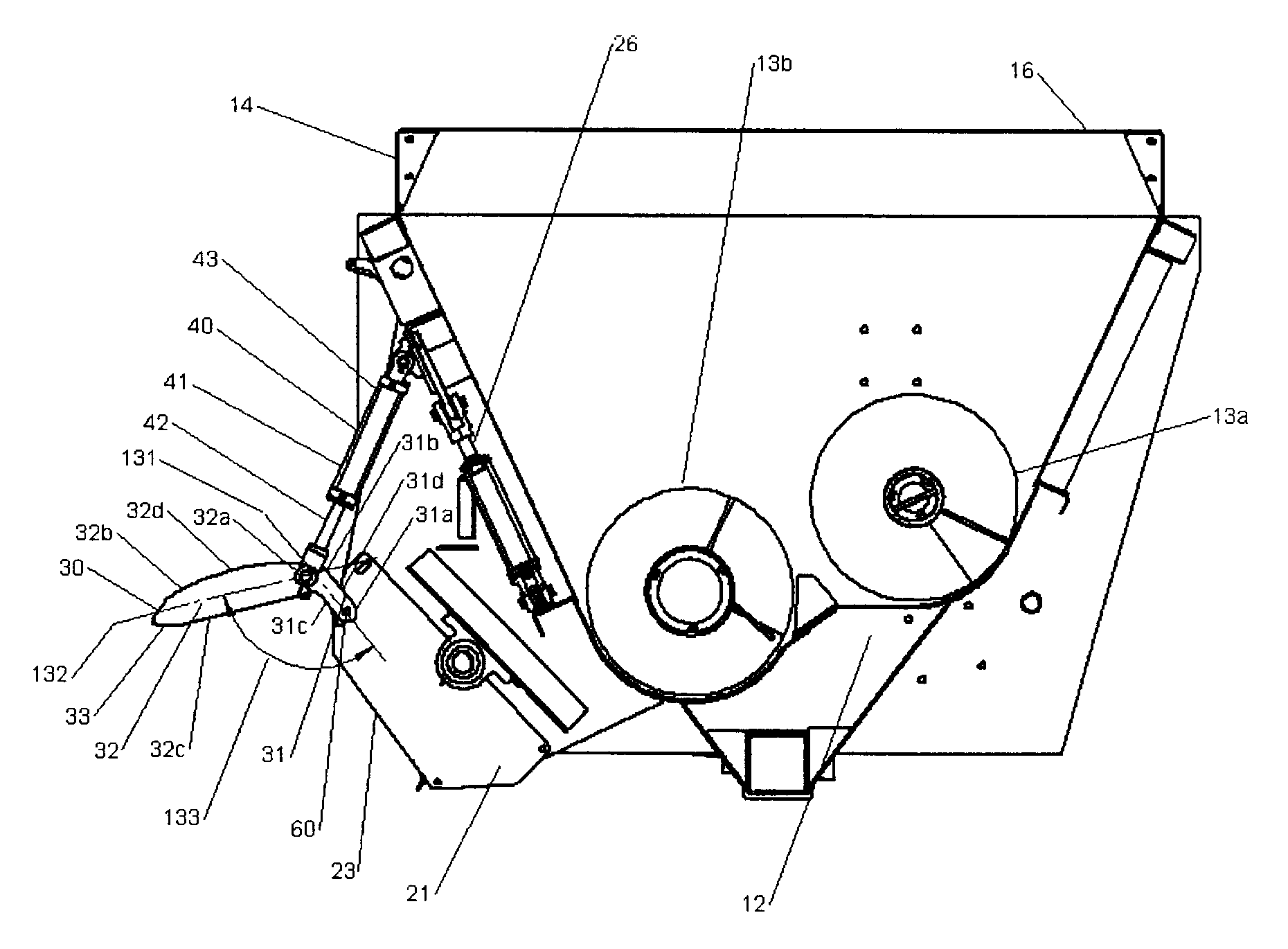
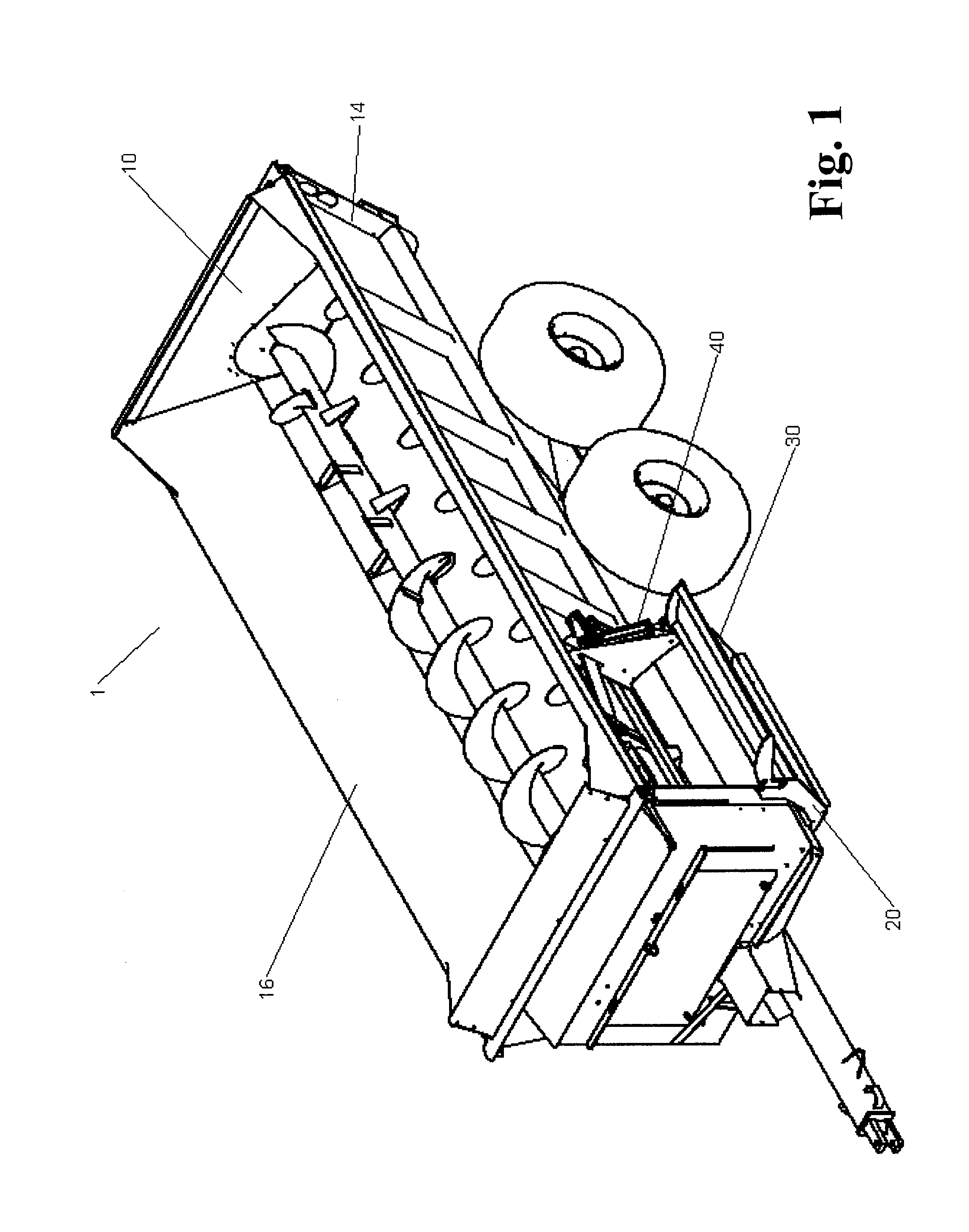
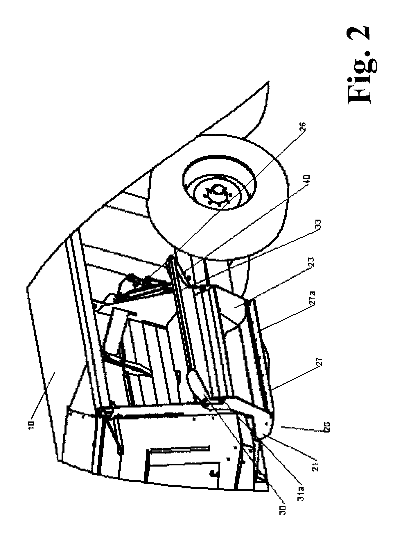
[0032]With reference to FIGS. 1, 2, 3A and 3B, one example of a spreader apparatus 1 for spreading material onto a target area is shown. The spreader apparatus 1 includes a container 10 and a discharge unit 20 that discharges the material onto a target area. In the depicted non-limiting example, the discharge unit 20 is provided at a side of the container 10. The material that is spread may include, for example, manure, compost, sand, municipal waste and fish food. However, other materials are possible.

[0033]The container 10 includes a floor 12, a sidewall 14, an open upper end 16 which receives the material and an outlet 18 through which the material from the container 10 moves to the discharge unit 20. Augers 13a, 13b disposed in the container 10 move the material from the container 10 to the discharge unit 20.

[0034]The spreader apparatus 1 shown in FIG. 1 is pulled by a tractor as a trailer. In an alternate embodiment shown in FIG. 6, the spreader apparatus 1 is instead arranged ...


PUM


Abstract

A spreading apparatus for spreading material onto a target area is disclosed. The spreading apparatus includes a container for the material, a discharge unit which discharges the material, a deflector door disposed on a discharge port of the discharge unit, a positioning device which positions the deflector door and a controller configured to control the deflector door so that the deflector door is positioned between a first closed position and a second open position. The material is substantially prevented from exiting through the discharge port when the deflector door is in the first position. The deflector door may further be positioned at a position between the first closed position and second open position to control a distance of the material discharged from the discharge port.

Description

BACKGROUND OF THE INVENTION[0001]1. Field of the Invention[0002]This invention relates to a spreader apparatus for spreading, among other materials, manure, compost, cut crop material, sand, municipal waste, fish food, or the like.[0003]2. Description of the Related Art[0004]Many mechanical arrangements have been devised for spreading material such as manure. A typical spreader apparatus includes a container having an opening for the reception therein of the material and an outlet for a discharge therethrough of the material to be spread on the desired area.[0005]In some conventional apparatuses, the spreader apparatus includes a material deflector that is provided near the discharge outlet to control the spread pattern and point of deposition of the material to be spread.[0006]However, the spreader apparatus typically has to travel to and from the location where the material is spread. For example, the spreading apparatus may have to travel over a roadway to get to the field. After...

Claims


Application Information

Patent Timeline
Patent Type & Authority Patents(United States)
IPC IPC(8): E01C19/20A01C3/06A01C19/00
CPCE01C19/2025A01C3/06
Inventor GIBSON, TODDCICCI, GEORGEHENRY, PATRICK
Owner KUHN NORTH AMERICA
Why Eureka
Try Eureka