
Speed sensor testing device and measurement method

Technology of a speed sensor and testing device

Active Publication Date: 2016-04-27
NINGBO CRRC TIMES TRANSDUCER TECH CO LTD
View PDF7 Cites 6 Cited by
  • Summary
  • Abstract
  • Description
  • Claims
  • Application Information

AI Technical Summary

Problems solved by technology

[0003] Application publication number is CN103675323A (application number is 201310639352.7) Chinese invention patent application "a magnetoelectric speed sensor and its testing device", in the disclosed speed sensor testing device, the sensor fixing table adjusts the slide seat through the air gap to adjust The air gap between the sensing end surface of the speed sensor and the tooth top surface of the test gear usually requires a feeler gauge to determine the air gap, and the adjustment steps are cumbersome. In addition, the speed sensor test device cannot realize the zero position of the input waveform of the speed sensor and the top of the test gear. The measurement of the surface centerline deviation makes the performance test of the speed sensor incomplete, and the corresponding speed test accuracy is not high

Method used


Image

  • Speed sensor testing device and measurement method
  • Speed sensor testing device and measurement method
  • Speed sensor testing device and measurement method

Examples


Embodiment Construction

[0067] The present invention will be described in further detail below in conjunction with the embodiments of the accompanying drawings.

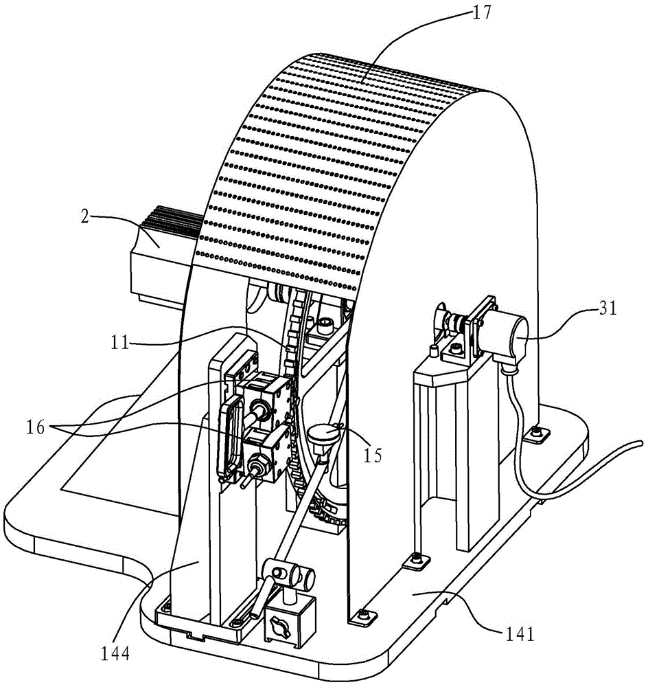
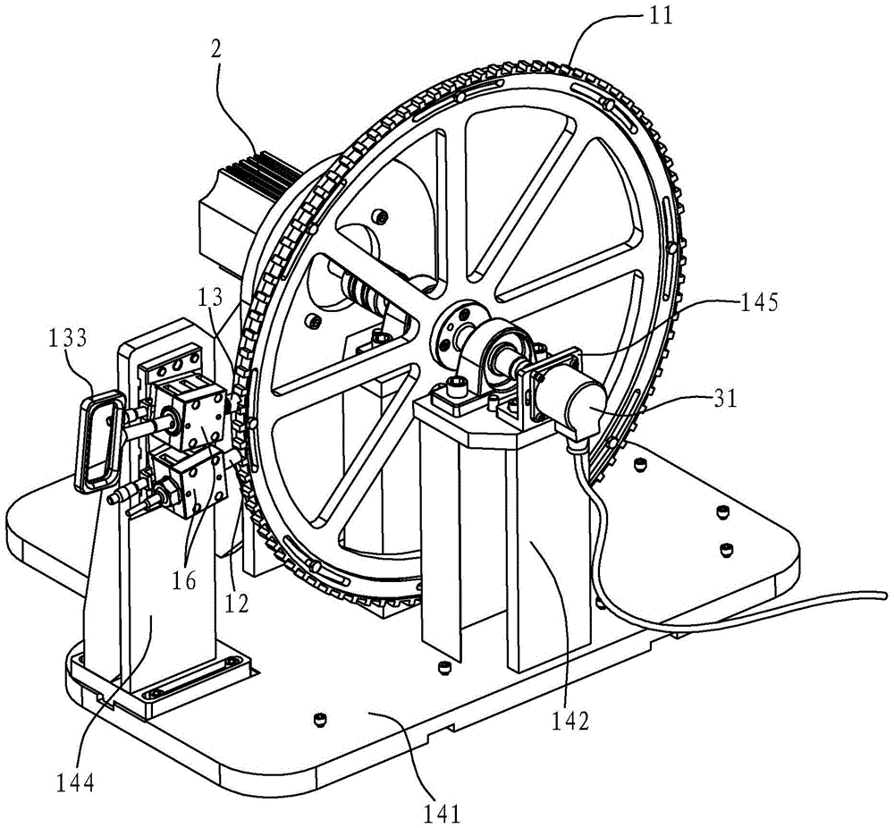
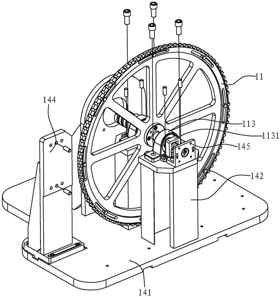
[0068] Such as Figure 1 to Figure 11 As shown, the speed sensor test device in this embodiment includes a test mechanism 1 for providing a structural basis for the speed sensor test, and a power mechanism 2 for providing power for the test mechanism 1, for realizing the output signal of the speed sensor 12 and Electrical system for gear rotation signal measurement 3.

[0069] Wherein the power mechanism 2 can adopt a mechanism that can provide power for the test mechanism 1 such as a motor and its matching motor control system. The ionization mechanism in this embodiment includes a DC brushed permanent magnet motor and its corresponding motor control system. The DC motor can choose the CDP3445 model of BALDOR. The power of the motor is 1.5kw, and the maximum speed is 1750r / min. The motor control system can display the current motor spee...


PUM


Abstract

The invention discloses a speed sensor testing device and a measurement method. The invention comprises a testing mechanism having a gear and a speed sensor, a power mechanism for driving a gear, and an electric system for measuring speed sensor output and a gear rotation signal. The testing mechanism comprises a gear positioning pin, and a measurement dial indicator. The measurement method comprises steps of calculating and obtaining the angle of a rotation signal waveform descending rim midpoint deviated from the gear top center line of the gear through measuring the rotation distance of the gear in a range of a gap between a tooth and a gear positioning pin by a dial indicator and combining with the electric level hopping of the gear rotation signal in an oscilloscope, utilizing a speed sensor to output the comparison between a waveform zero position and the gear rotation signal waveform descending rim midpoint point, calculating to obtain the angle of the waveform zero position outputted by the descending rim midpoint of the gear rotation signal waveform so as to obtain the deviation angle between the zero position of the waveform outputted by the sensor and the gear top surface center line on the gear. The invention improves the comprehensiveness of the speed sensor.

Description

technical field [0001] The present invention relates to a speed sensor testing device, and also relates to a measuring method of the speed sensor testing device. The measuring method of the speed sensor testing device can calculate the deviation between the zero position of the output waveform of the measuring speed sensor and the center line of the addendum surface of the speed measuring gear. Background technique [0002] A large number of speed sensors are used in the field of rail transit. Accurate and comprehensive testing of the parameters of the speed sensor by using the test device is the basic guarantee for mastering its working performance. For example, the Chinese invention patent application with the application publication number CN104360104A (application number 201410647114.5) "Universal Test Device for Speed ​​Sensors Under Various Environmental Conditions", the test device disclosed therein can test the working performance of the speed sensor. [0003] Applic...

Claims


Application Information

Patent Timeline
Patent Type & Authority Applications(China)
IPC IPC(8): G01P21/02G01B21/22G01B21/16
CPCG01B21/16G01B21/22G01P21/02
Inventor 陈增贤张燕亮陈太龙樊宁广李军伟刘丹
Owner NINGBO CRRC TIMES TRANSDUCER TECH CO LTD
Learn More