Hot bulge forming die apparatus

一种热胀、热膨胀的技术,应用在热胀成形装置领域,能够解决生产成本变高等问题,达到抑制生产成本、尺寸稳定、提高定位的精度的效果

Inactive Publication Date: 2011-02-02
HONDA MOTOR CO LTD
View PDF5 Cites 11 Cited by
  • Summary
  • Abstract
  • Description
  • Claims
  • Application Information

AI Technical Summary

Problems solved by technology

[0016] However, in this second method, the size of the mold and peripheral equipment will increase, and the production cost will increase.

Method used


Image

  • Hot bulge forming die apparatus
  • Hot bulge forming die apparatus
  • Hot bulge forming die apparatus

Examples


Embodiment Construction

[0048] One embodiment of the present invention will be described below with reference to the drawings.

[0049] figure 1 It is a schematic configuration diagram showing the operation of the thermal expansion molding apparatus 1 to which the thermal expansion molding die according to one embodiment of the present invention is applied.

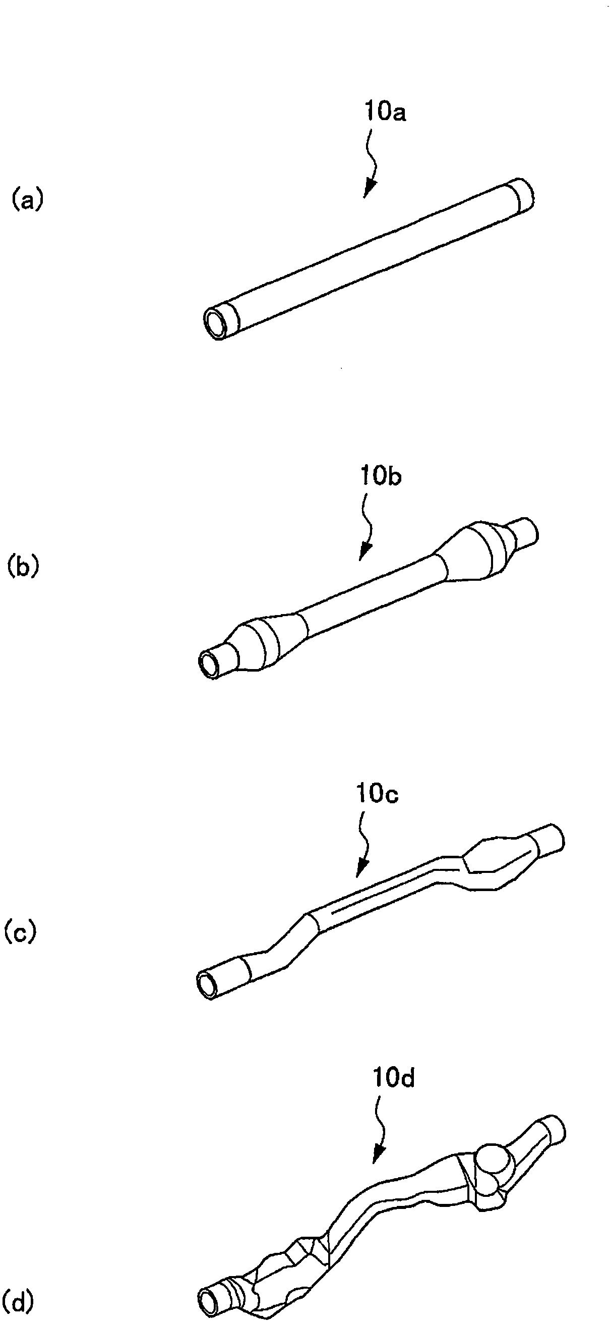
[0050] figure 2 It is a perspective view showing tubular blanks 10 a to 10 d as workpieces to be formed by the thermal expansion forming apparatus 1 .

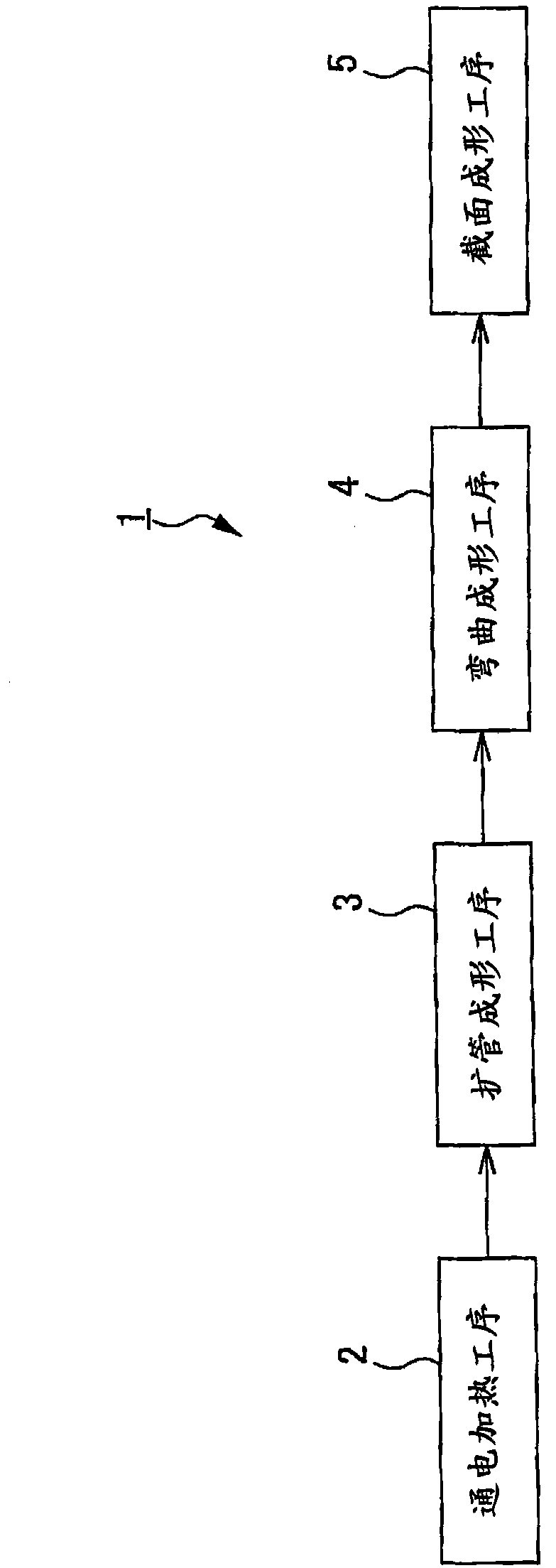
[0051] The thermal expansion forming device 1 sequentially executes the energization heating step 2, the tube expansion forming step 3 and the bending forming step 4 as a preliminary heating step, and the cross-section forming step 5 as a final forming step.

[0052] Specifically, in the energization heating step 2, the aluminum alloy tubular material 10a extending substantially linearly is heated.

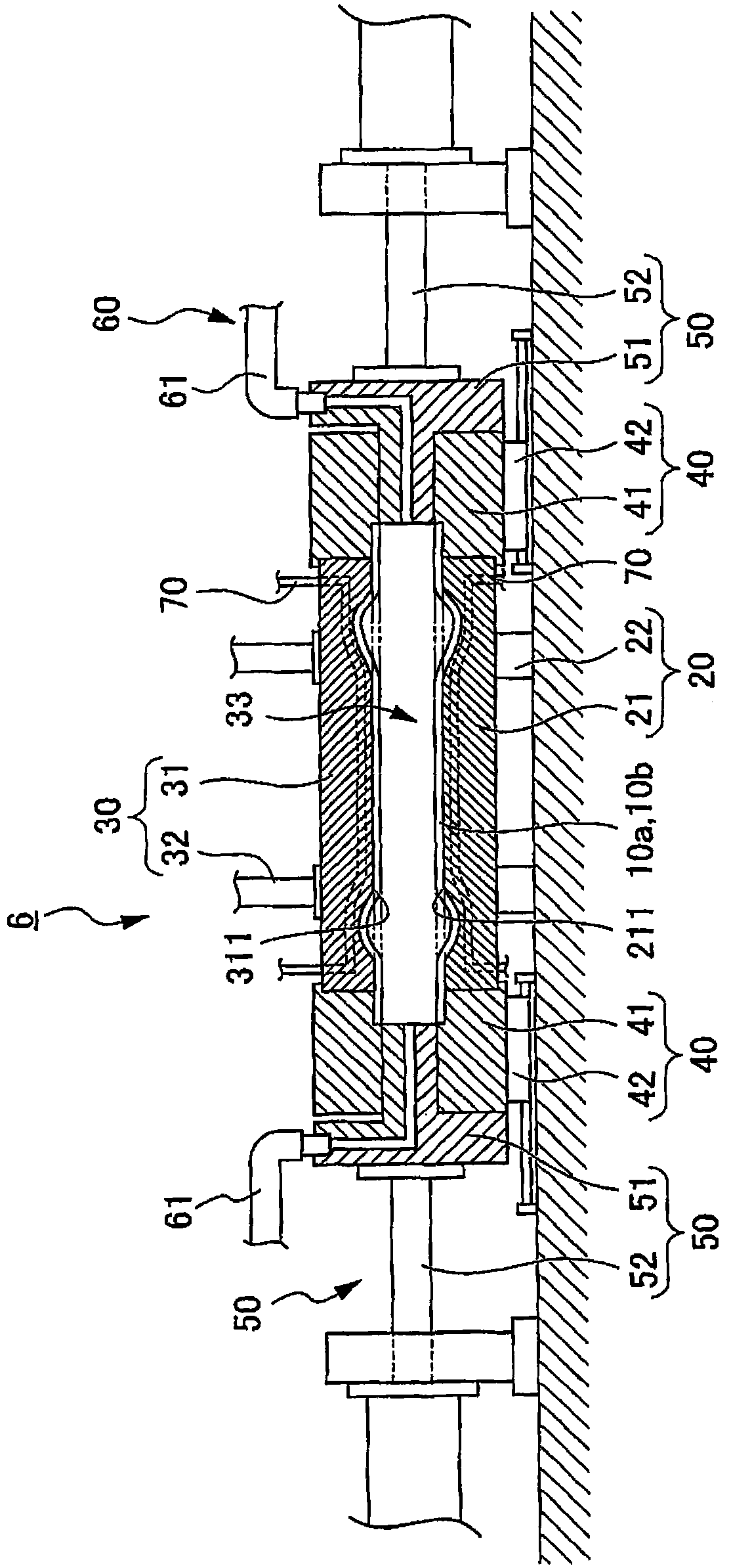
[0053] In the pipe expansion forming step 3, the first expansion forming device 6 (refer to ...


PUM


Abstract

The invention provides a hot bulge forming die apparatus which can suppress an increase in production costs. A hot bulge forming die apparatus forms a preheated tubular material 10a into a tubular material 10d. The hot bulge forming die apparatus includes a lower die 21B having a cavity surface 211B and an upper die 31B having a cavity surface 311B. An elongated hole 215 is formed in a circumferential edge portion 215 of the lower die 21B so as to extend outwards, and a projection 315 is formed on a circumferential edge portion 314 of the upper die 31B so as to fit in the elongated hole 215. When the dies are clamped together, the projection 315 formed on the circumferential edge portion 314 of the upper die 31B fits in the elongated hole 215 formed in the circumferential edge portion 214of the lower die 21B.

Description

technical field [0001] The invention relates to a thermal expansion forming device. Specifically, it relates to a thermal expansion forming device for forming a preheated tubular workpiece. Background technique [0002] Conventionally, thermal expansion molding is known in which a tubular workpiece is formed by supplying high-pressure air into a cavity of a mold. [0003] Specifically, in this thermal expansion molding, for example, a tubular work is heated in advance, and the tubular work is placed between a pair of dies. Next, while restraining both ends of the workpiece in the longitudinal direction, the mold is clamped and high-pressure air is supplied into the cavity, and the workpiece is pressed against the cavity surface of the mold by the pressure of the air. Then, the workpiece is cooled by the mold by maintaining this state for a certain period of time, and then the mold is opened to take out the molded workpiece from the mold (for example, refer to Patent Docume...

Claims


Application Information

Patent Timeline
Patent Type & Authority Applications(China)
IPC IPC(8): B21D37/10B21D26/02
CPCB21D26/047B21D37/16B21D37/12Y10T29/49805
Inventor 石原好光山本大介狩野贵之
Owner HONDA MOTOR CO LTD
Why Eureka
Try Eureka