
Negative voltage slope control circuit

A control circuit and negative voltage technology, applied in the field of negative voltage slope control circuit, can solve the problems of erasing voltage jump, ripple, etc., and achieve the effect of reliable control

Active Publication Date: 2011-02-02
SHANGHAI HUAHONG GRACE SEMICON MFG CORP
View PDF5 Cites 12 Cited by
  • Summary
  • Abstract
  • Description
  • Claims
  • Application Information

AI Technical Summary

Problems solved by technology

[0007] In order to overcome the problem in the above-mentioned prior art that the erasing voltage is non-linear and cause unnecessary ripples due to jumps, the main purpose of the present invention is to provide a negative voltage slope control circuit, so that the erasing voltage drops more smoothly, avoiding The erasing voltage existing in the prior art will produce jumps and form ripples

Method used


Image

  • Negative voltage slope control circuit
  • Negative voltage slope control circuit
  • Negative voltage slope control circuit

Examples


Embodiment Construction

[0030] The implementation of the present invention is described below through specific examples and in conjunction with the accompanying drawings, and those skilled in the art can easily understand other advantages and effects of the present invention from the content disclosed in this specification. The present invention can also be implemented or applied through other different specific examples, and various modifications and changes can be made to the details in this specification based on different viewpoints and applications without departing from the spirit of the present invention.

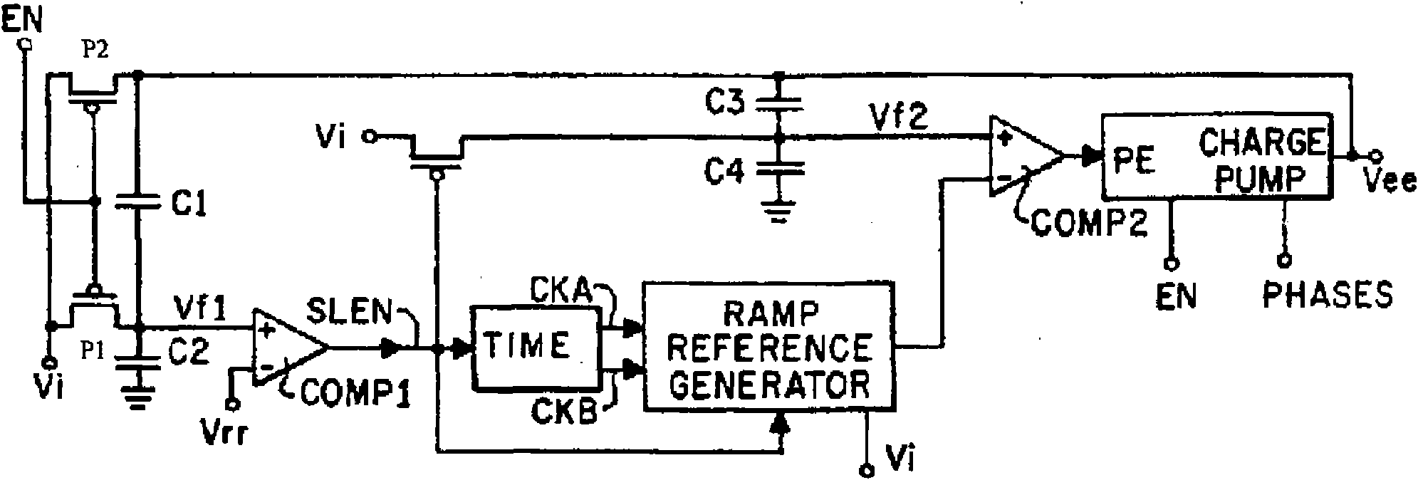
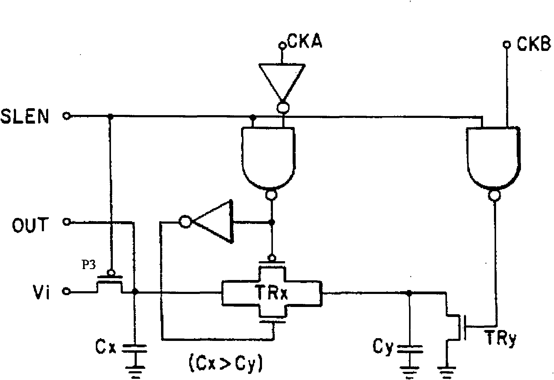
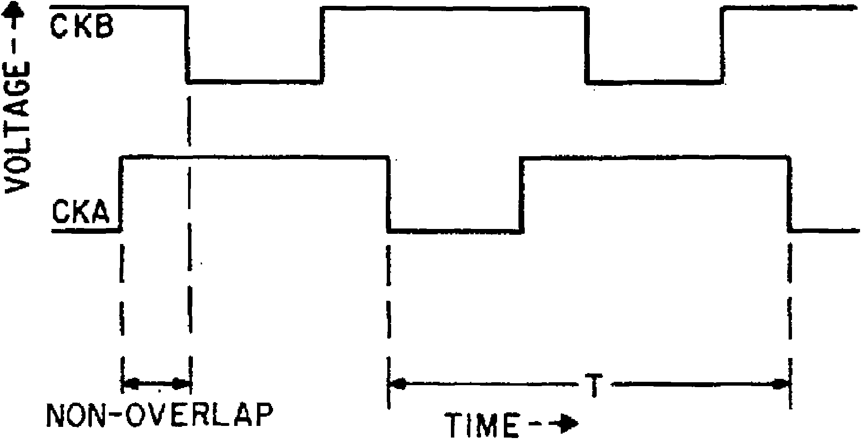
[0031] figure 2 It is a circuit structure diagram of a first preferred embodiment of a negative voltage slope control circuit of the present invention. Such as figure 2 As shown, a negative voltage slope control circuit of the present invention is used to control the erasing voltage slope of a non-volatile memory (EEPROM, such as a flash memory), including: an oscillator 101, a first swi...


PUM


Abstract

The invention discloses a negative voltage slope control circuit for controlling erasing voltage of a nonvolatile memory. The negative voltage slope control circuit comprises an oscillator, a first switch tube, a benchmark constant-current source, a mirror image constant-current source, a transient control capacitor and a second switch tube. The oscillator is used for generating periodic wave; the first switch tube is connected with the oscillator and is used for obtaining control periodic wave to control the connection and disconnection of the first switch tube; the benchmark constant-current source is connected with the first switch tube; the mirror image constant-current source is connected with the first switch and is used for mirroring the current of the benchmark constant-current source; the transient control capacitor is connected with the mirror image constant-current source; the second switch tube is connected between the transient control capacitor and the mirror image constant-current source; and the erasing voltage is output through the second switch tube. The erasing voltage obtained by the negative voltage slope control circuit avoids generating abrupt change to form ripple wave, thereby the defects in the prior art are overcome.

Description

technical field [0001] The present invention relates to a negative voltage slope control circuit, in particular to a negative voltage slope control circuit for controlling the slope of the erasing voltage of a nonvolatile memory. Background technique [0002] Semiconductor memories can be classified into volatile memories and nonvolatile memories. Electrically erasable / programmable non-volatile memory (EEPROM) is a type of non-volatile memory, which is characterized in that data can still be retained without power, and can be erased and modified when needed. To erase an EEPROM cell, it is often necessary to apply a negative voltage to its control gate (erase voltage). Therefore, in order to erase and write accurately, it is necessary to effectively control the negative voltage slope. [0003] For the prior art, please refer to US Patent No. 5,168,174 (Negative-Voltage Charge Pump With Feedback Control), which discloses a negative voltage slope control circuit. Figure 1a i...

Claims


Application Information

Patent Timeline
Patent Type & Authority Applications(China)
IPC IPC(8): G11C16/30H02M3/07
Inventor 杨光军
Owner SHANGHAI HUAHONG GRACE SEMICON MFG CORP
Learn More