Filter coupling structure with adjustable capacity

A coupling structure and filter technology, which is applied to waveguide devices, electrical components, connecting devices, etc., can solve the problems of large adjustment range, waste of materials, troublesome disassembly of cover plates, etc., and achieve the effect of convenient production

Active Publication Date: 2011-02-02
MOBILE ANTENNA TECH SHENZHEN +5
View PDF4 Cites 14 Cited by
  • Summary
  • Abstract
  • Description
  • Claims
  • Application Information

AI Technical Summary

Problems solved by technology

Although the metal sheet in the above coupling structure is simple, easy to form, and has a large adjustment range, and to a certain extent brings convenience to the filter design and cavity layout, once the cover plate is assembled, i

Method used


Image

  • Filter coupling structure with adjustable capacity
  • Filter coupling structure with adjustable capacity
  • Filter coupling structure with adjustable capacity

Examples


Embodiment Construction

[0023] In order to make the object, technical solution and advantages of the present invention clearer, the present invention will be further described in detail below in conjunction with the accompanying drawings and embodiments. It should be understood that the specific embodiments described here are only used to explain the present invention, not to limit the present invention.

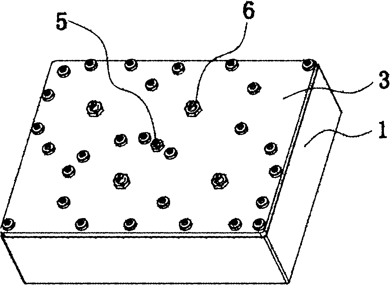
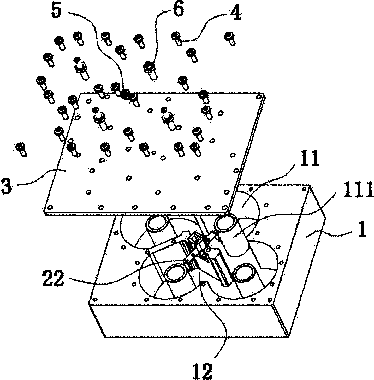
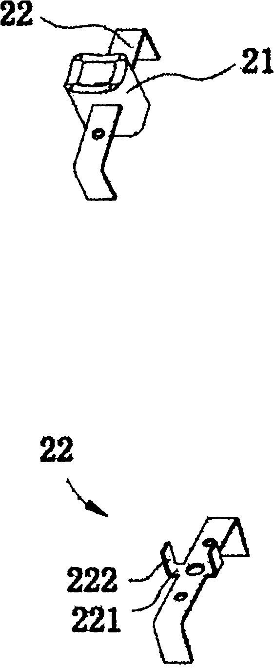
[0024] refer to figure 1 , figure 2 As shown, it is a preferred embodiment of the present invention. Taking a specific coaxial cavity bandpass filter as an example, it includes a cavity 1, a coupling structure 2, a cover plate 3, a plurality of connecting cover plates 3 and the cavity 1 nut 4, the first adjusting screw 5 and the second adjusting screw 6.

[0025] The cavity 1 is integrally formed by aluminum alloy, and its surface is electroplated, showing a rectangular block structure. Inside the cavity 1, there are four resonant cavities 11 with basically the same size. Each resonant cavity ha...


PUM


Abstract

The embodiment of the invention discloses a filter coupling structure with adjustable capacity. The filter coupling structure is arranged in a cavity with at least two resonant cavities. The filter coupling structure contains a coupling structure which is arranged between the resonant cavities and contains a plastic part and a metal sheet, wherein a part of the metal sheet is embedded in the plastic part, two opposite projection parts extend from the two sides of the center of the metal sheet; the projection parts are embedded in the plastic part; a first adjusting screw rod penetrates a cover plate, and the cover plate are matched with the cavity; and the first adjusting screw rod is arranged between the two opposite projection parts. The invention provides a simple and realizable filterwhich is easy to form and the filter coupling structure with adjustable capacity which can be adjusted without being disassembled and have wide adjusting range, so as to satisfy the demand of the out-of-band rejection degree.

Description

technical field [0001] The invention belongs to radio frequency and microwave filters in the field of wireless communication, in particular to a filter adjustable capacitive coupling structure. Background technique [0002] With the development of the mobile communication industry, radio frequency resources are becoming more and more tight, and the frequency bands used by various communication systems are getting closer and closer, which may easily interfere with each other and cause communication equipment to fail to work normally. With high out-of-band suppression requirements, such as duplexers, at least 85dB suppression is required between the transmit channel and the receive channel. Achieving higher out-of-band rejection is achieved by introducing capacitive or inductive coupling between multiple non-adjacent resonators to generate multiple transmission zeros. The realization of the conventional inductive coupling structure can adjust the coupling amount, which is ben...

Claims


Application Information

Patent Timeline
IPC IPC(8): H01P1/208H01P5/00
Inventor 刘伟张卫征叶荣顾国治
Owner MOBILE ANTENNA TECH SHENZHEN
Why Eureka
Try Eureka