Probe base

A technology of probes and ribs, which is applied in the field of probe bases, can solve the problems of high stability, inapplicability to the installation of probe bases, and the inability to give components, etc., to achieve high stability, simple manufacturing, and reduce stress formation.

Inactive Publication Date: 2013-04-10
REHAU AG & CO
View PDF1 Cites 0 Cited by
  • Summary
  • Abstract
  • Description
  • Claims
  • Application Information

AI Technical Summary

Problems solved by technology

[0003] The disadvantage of this solution is that the configuration of the ribs neither gives high stability to the component nor is it suitable for simple installation of the probe base in the drilled hole

Method used


Image

  • Probe base
  • Probe base
  • Probe base

Examples


Embodiment Construction

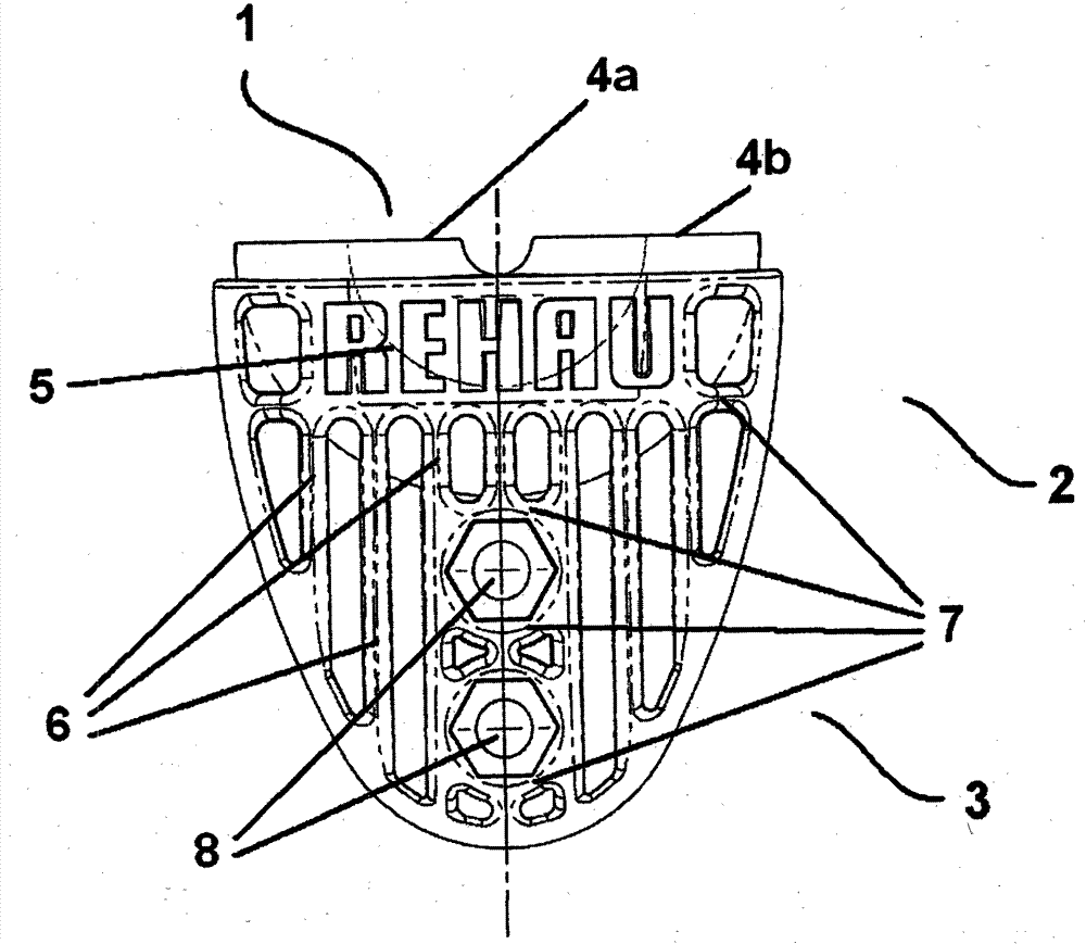
[0035] exist figure 1 A plan view of a probe base 1 according to the invention is shown in . The probe base 1 has a fluid guiding part 2 and a base part 3 . Tube elbow ends 4 a , 4 b are formed on the fluid guide part 2 for connecting the probe base 1 to a tube, not shown here.

[0036] exist figure 1 The pipe bend 5 shown in is an integral part of the fluid guide part 2 . The rib 6 is arranged on the probe base 1 such that the rib extends substantially between the fluid guiding part 2 and the base part 3 in the direction of the axis of the tube, not shown here.

[0037] Furthermore, connecting ribs 7 are arranged between the ribs 6 and extend substantially perpendicular to the ribs 6 . Two such probe bases 1 can be connected in pairs by means of connecting elements through through holes 8 . Mechanisms for force transmission can also be mounted on the through-opening 8 .

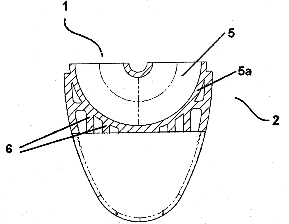
[0038] according to figure 2 , shown in a cross-sectional view, a pipe bend 5 is formed in the fl...


PUM


Abstract

The present invention relates to a probe base (1) for a device for geothermal energy generation or geothermal energy storage, which can be connected to pipes (9), and which comprises a fluid guide section (2) and a base section (3) positioned opposite thereof, wherein ribs (6) are disposed on the fluid guide section (2) and on the base section (3). The invention is characterized in that the ribs (6) extend substantially in the axial direction of the connected pipes (9) between the fluid guide section (2) and the base section (3).

Description

technical field [0001] The invention relates to a probe base for use in a device for obtaining or storing geothermal heat, said probe base being connectable to a pipe and consisting of a fluid guiding part and a base part located opposite the fluid guiding part, wherein Ribs are provided on the fluid guiding portion and the base portion. Furthermore, the invention relates to a device for obtaining or storing geothermal heat, said device being provided with a probe base. Finally, the invention also relates to a heating or cooling system with a device for obtaining or storing geothermal heat. Background technique [0002] Probe bases are known from the prior art, which are used to obtain or store geothermal heat and consist of a fluid-guiding part and a base part opposite the fluid-guiding part, wherein ribs are arranged between the fluid-guiding part and on the base part. Thus US D488486 S shows a probe base with ribs. [0003] A disadvantage of this solution is that the ...

Claims


Application Information

Patent Timeline
Patent Type & Authority Patents(China)
IPC IPC(8): F24J3/08
CPCY02E10/125F24J3/083F24T10/15Y02E10/10
Inventor 丹尼尔·戈特沙尔克马里奥·普希克
Owner REHAU AG & CO
Why Eureka
Try Eureka