Drive means and chain drive

A driving device and chain transmission technology, which is applied in the direction of transmission devices, belts/chains/gears, escalators, etc., can solve problems such as interference, damage to the stability of the conveyor belt/escalator, and bearing wear, so as to achieve durable costs, avoid wear and tear. Possibly with the effect of corrosion

Inactive Publication Date: 2013-08-07
KETTEN WULF BETRIEBS GMBH & CO KG
View PDF2 Cites 0 Cited by
  • Summary
  • Abstract
  • Description
  • Claims
  • Application Information

AI Technical Summary

Problems solved by technology

This unloaded branch can shake into vibrations under unfavorable operating parameters, thus compromising the running stability of the conveyor belt / escalator in the meantime
Since many deflections of the swivel lever can cause rapid wear of the individual bearings and cause disturbing noises,

Method used


Image

  • Drive means and chain drive
  • Drive means and chain drive
  • Drive means and chain drive

Examples


Embodiment Construction

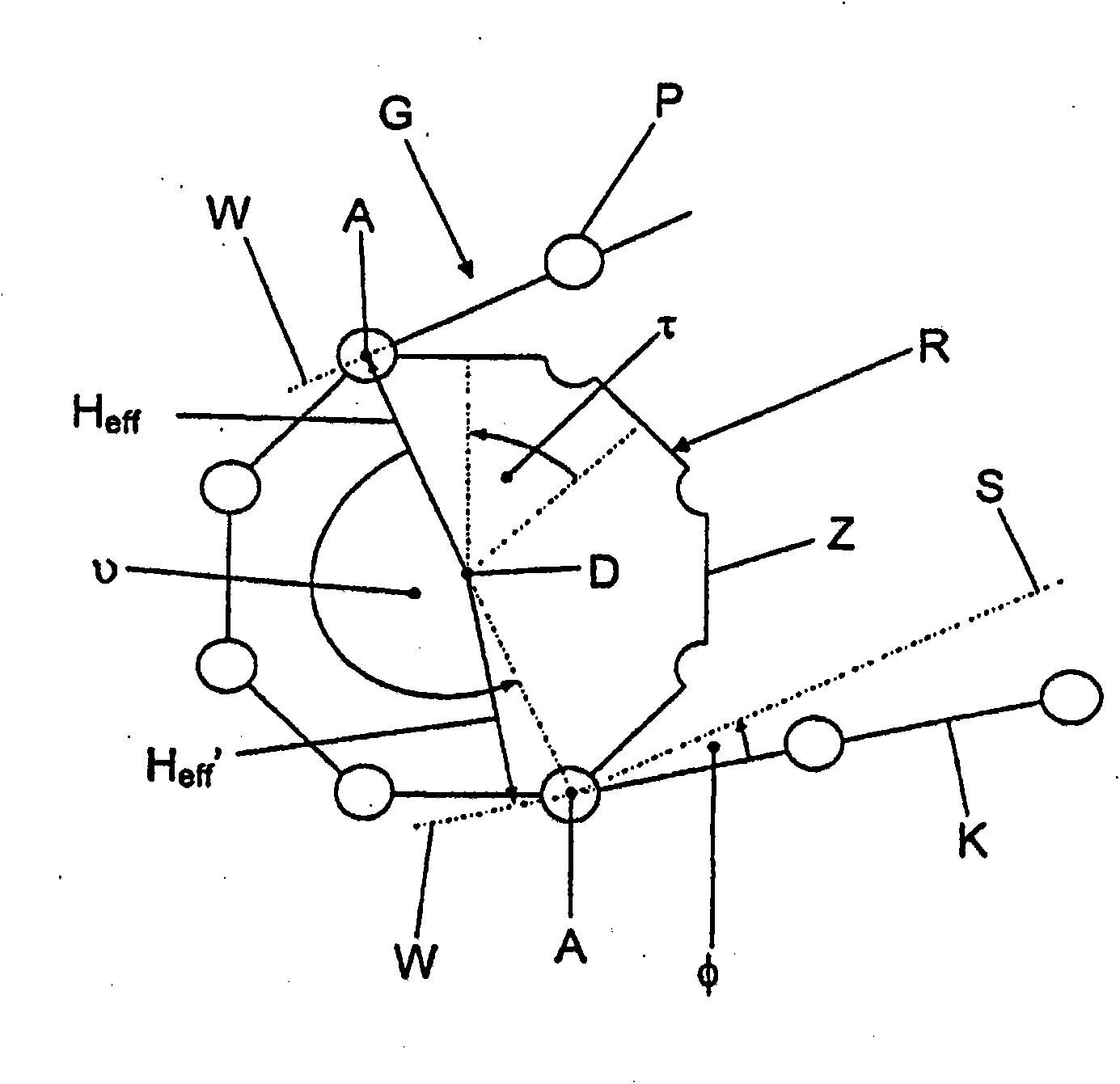
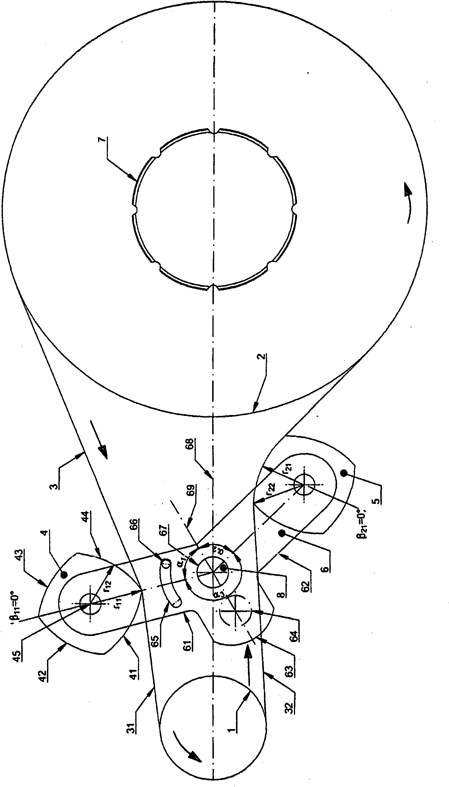
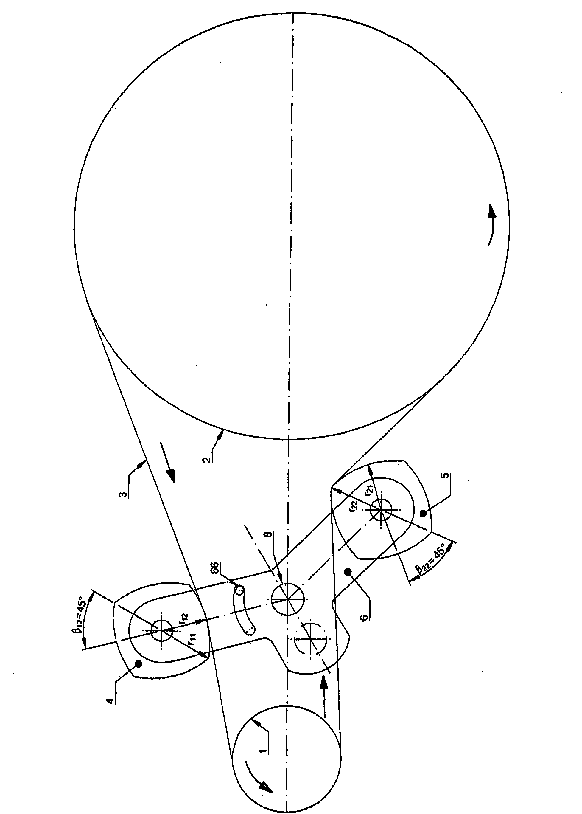
[0084] The drive according to the invention basically comprises a first traction device wheel 1 , a second traction device wheel 2 , a traction device 3 , a first equalizing wheel 4 , a second equalizing wheel 5 and a rocker 6 .

[0085] The chain drive according to the invention comprises at least one drive according to the invention and at least one sprocket 7 which is driven by the drive. In particular, the chain drive according to the invention comprises a conveyor chain, preferably a stair chain or a tread chain, on which a plurality of escalator steps or treads are mounted, and the chain drive according to the invention also comprises another ( not shown) sprockets, where the conveyor chain runs on sprocket 7 and another sprocket.

[0086] The traction device 3 is, for example, a chain, preferably a roller chain, arranged around the first traction device wheel 1 and the second traction device wheel 2 in the form of an endless chain. This forms a first part of the tracti...


PUM


Abstract

Drive means for the polygonally-compensated drive of a sprocket, comprising two pulling means wheels (1, 2), a pulling means (3) running on them with an top span (31) and a bottom span (32), and a tensioning means acting on the pulling means (3), wherein the tensioning means comprises a first non-circular compensation wheel (4), which can come into contact with the top span (31), a second non-circular compensation wheel (5), which can come into contact with the bottom span (32), a rocker (6) adapted for rotatably receiving the first compensation wheel (4) and the second compensation wheel (5), wherein the rocker (6) is pivotably supported on a fixed bearing. The invention also relates to a chain drive, comprising at least a sprocket (7), a drive means, wherein the sprocket (7) is driven by the drive means, wherein the drive means is a drive means according to at least one of the claims 1 to 17.

Description

technical field [0001] The invention relates to a drive for a polygonally balanced drive of sprockets according to the preamble of claim 1 and to a chain drive according to the preamble of claim 18 . Background technique [0002] In order to explain the concepts "multi-corner effect" and "multi-corner equalization" first, they are explained as follows. [0003] figure 1 The link chain G and the sprocket R partially surrounded by it are schematically shown in . The articulated chain G comprises a plurality of mutually articulated chain links K, which are articulated to each other via a point of pivot P. The sprocket K shown as an example has 8 teeth Z between which tooth gaps are arranged. The pivot point P is embedded in said tooth space. The indexing angle τ between two teeth or between two tooth slots is 45° in the example shown [0004] In addition, in figure 1 On the underside of the sprocket, a lead-in angle φ is drawn, which can be caused, for example, by deflect...

Claims


Application Information

Patent Timeline
Patent Type & Authority Patents(China)
IPC IPC(8): F16H7/12F16H7/06F16H7/08
CPCF16H2007/0874F16H55/303F16H7/06B66B23/022B65G23/06
Inventor B·格罗贝尔
Owner KETTEN WULF BETRIEBS GMBH & CO KG
Why Eureka
Try Eureka