Supercharge Your Innovation With Domain-Expert AI Agents!

Diffraction optical element and method for manufacturing same

A technology of diffractive optical elements and diffraction gratings, applied in optical elements, diffraction gratings, optics, etc., can solve the problems of MTF characteristic dispersion and inability to mass-produce white diffractive optical elements, so as to ensure low cost and high reliability Effect

Inactive Publication Date: 2011-02-02
PANASONIC CORP
View PDF2 Cites 11 Cited by
  • Summary
  • Abstract
  • Description
  • Claims
  • Application Information

AI Technical Summary

Problems solved by technology

In particular, when the cover layer is formed by the "pad printing method" which is low-cost and suitable for mass production, since a part of the cover layer located in the above-mentioned concave part tends to become thinner, the MTF characteristic is dispersed, so that it cannot be mass-produced. The issue of producing white diffractive optical elements with good optical characteristics

Method used


Image

  • Diffraction optical element and method for manufacturing same
  • Diffraction optical element and method for manufacturing same
  • Diffraction optical element and method for manufacturing same

Examples


Embodiment Construction

[0030] Hereinafter, embodiments of a diffractive optical element employing the present invention will be described with reference to the drawings.

[0031] (First Embodiment) First, an embodiment using a diffractive optical element of the present invention will be described.

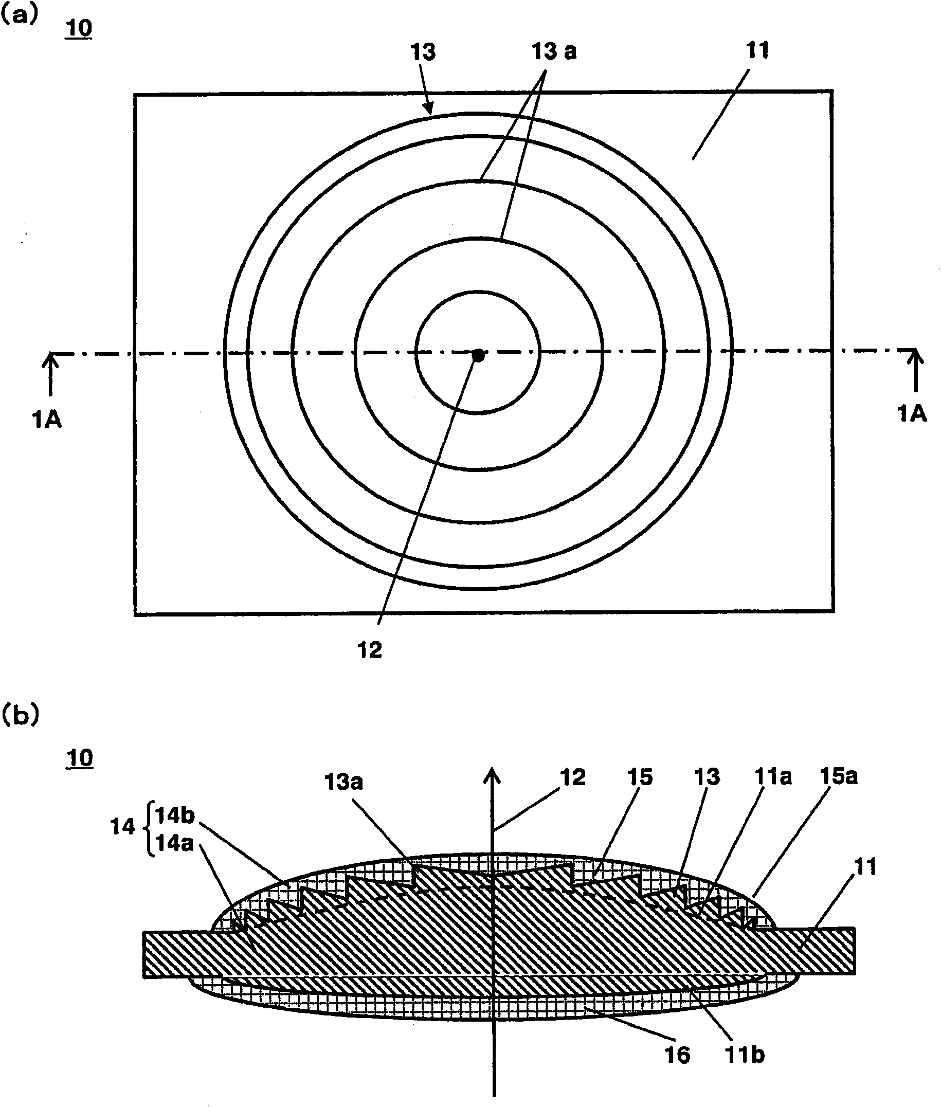
[0032] refer to figure 1 . figure 1 (a) is a plan view of the diffractive optical element 10 in this embodiment, figure 1 (b) is figure 1 1A-1A line sectional view in (a).

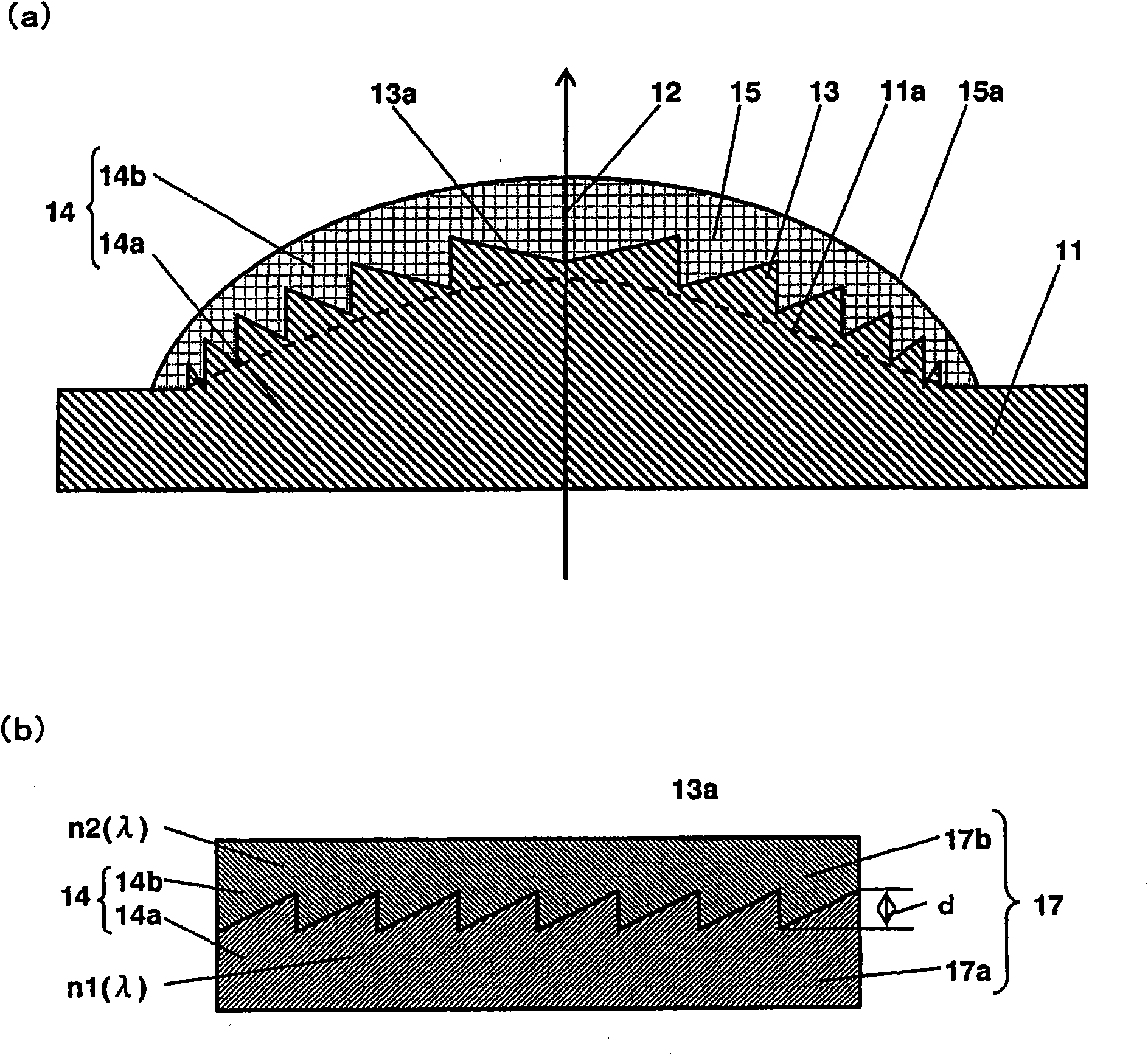
[0033] The diffractive optical element 10 in this embodiment, such as figure 1 As shown in (a) and (b), a lens base 11 (the lens base 11 is provided with a blazed diffraction grating 13 on the aspherical surface (first surface 11a)) and an optical adjustment layer 15 (the optical adjustment layer 15 covers the diffraction grating 13. The lens substrate 11 is formed by the first material 14a; the optical adjustment layer 15 is formed by the second material 14b whose refractive index is greater than the first material 14a.As a who...


PUM


Abstract

A diffraction optical element comprises a lens base (11) provided with a blazed diffraction grating (13) on an aspheric surface (11a) and an optical adjusting layer (15) covering the diffraction grating (13). The lens base (11) is formed of a first material (14a), and the optical adjusting layer (15) is formed of a second material (14b) having a higher refractive index than the first material (14a). The diffraction grating (13) includes plural ring zones arranged concentrically with an optical axis as a center. The height of each of the ring zones with respect to the aspheric surface (11a) of the lens base (11) is expressed by an increasing function of a distance r from the optical axis. The increasing function is expressed by a phase polynomial with the distance r as a variable, and the size of the phase polynomial is 3 / 4p or more and 7 / 4p or less when the distance r is zero.

Description

technical field [0001] The present invention relates to a diffractive optical element capable of effectively concentrating white light and suitable for mass production and a manufacturing method thereof. Background technique [0002] In recent years, with the advancement of digital technology, electronic devices such as cameras and video recorders that obtain image information as digital information have become more highly functional in the form of portable information devices and information appliances. With the increase in functionality of electronic devices such as cameras and video recorders, it is urgently required to reduce the weight, thickness, and cost of optical components such as lenses and optical systems used. [0003] Forming the condensing lens used in optical systems such as cameras and video recorders as a diffractive optical element eliminates the need to use multiple aspheric lenses with complex surface shapes. In this way, after the diffraction grating i...

Claims


Application Information

Patent Timeline
Patent Type & Authority Applications(China)
IPC IPC(8): G02B5/18
CPCG02B5/1852G02B27/0018G02B5/1895
Inventor 是永继博西胁青儿
Owner PANASONIC CORP
Features
  • R&D
  • Intellectual Property
  • Life Sciences
  • Materials
  • Tech Scout
  • Unparalleled Data Quality
  • Higher Quality Content
  • 60% Fewer Hallucinations
Learn More