Cooling fluid temperature control system for testing engine performance

A technology of temperature control system and coolant, which is applied in the direction of engine testing, machine/structural component testing, measuring devices, etc. It can solve the problems of large engine gap, ineffective exhaust, and inability to truly reflect the engine testing requirements, etc. To achieve the effect of increasing the water flow in and out and reducing the pressure difference between the water in and out

Active Publication Date: 2011-02-09
BEIQI FOTON MOTOR CO LTD
View PDF5 Cites 24 Cited by
  • Summary
  • Abstract
  • Description
  • Claims
  • Application Information

AI Technical Summary

Problems solved by technology

Although this method can achieve the purpose of controlling the cooling of the engine, it cannot effectively control the water pressure, and when the temperature of the coolant is controlled at a boiling point of about 100°C, a large amount of water vapor will be generated in the engine and water circulation, and the exhaust cannot be effectively exhausted. There is a large gap in the actual condition of the whole vehicle, and the actual cooling capacity of the engine cannot be fully inspected and verified, and the test results cannot truly reflect the engine test requirements

Method used


Image

  • Cooling fluid temperature control system for testing engine performance
  • Cooling fluid temperature control system for testing engine performance
  • Cooling fluid temperature control system for testing engine performance

Examples


Embodiment Construction

[0054] Below in conjunction with accompanying drawing, structural principle and working principle of the present invention are specifically described:

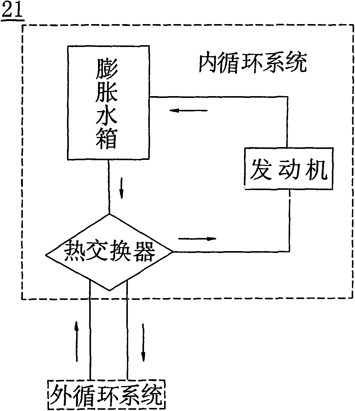
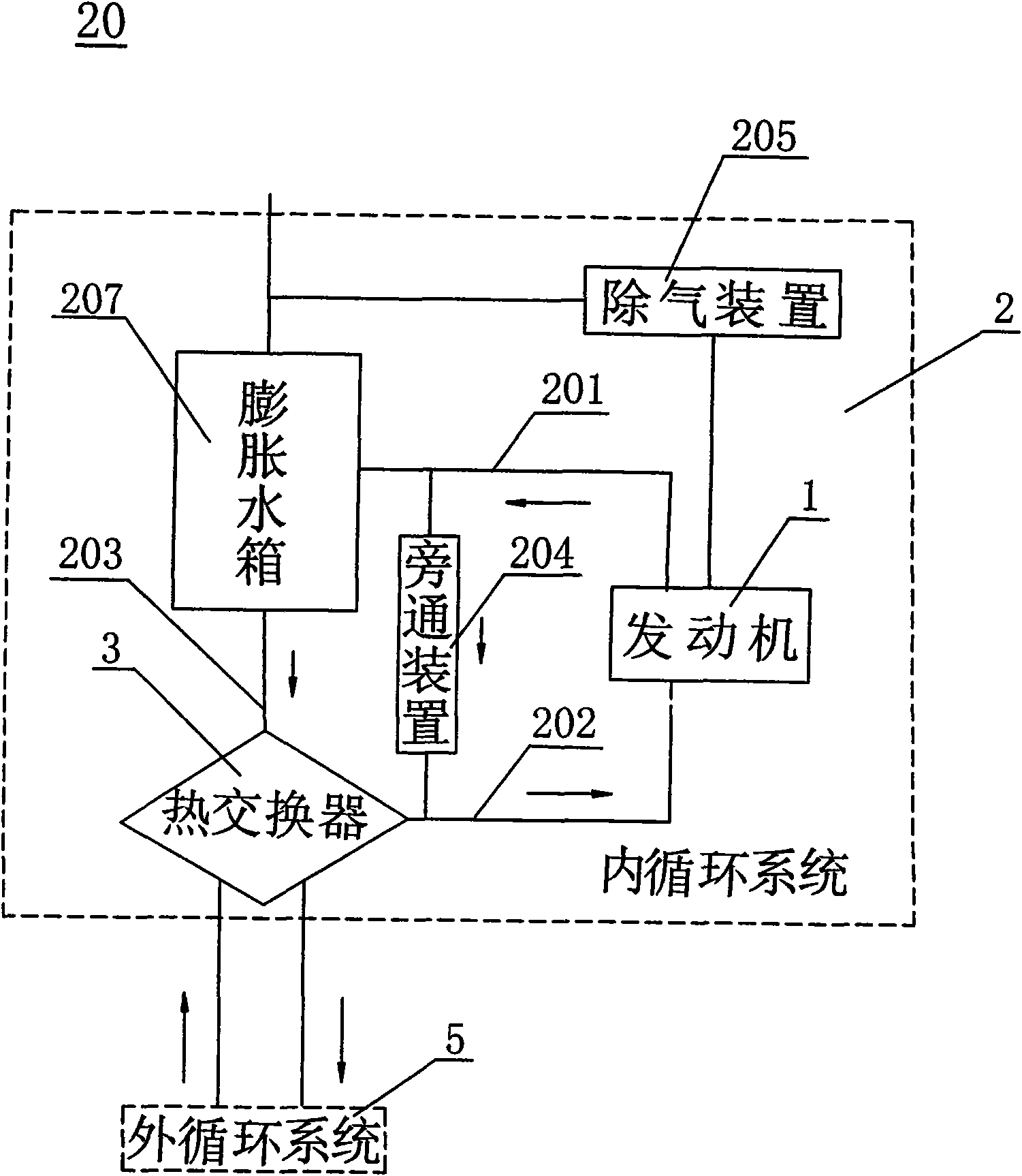
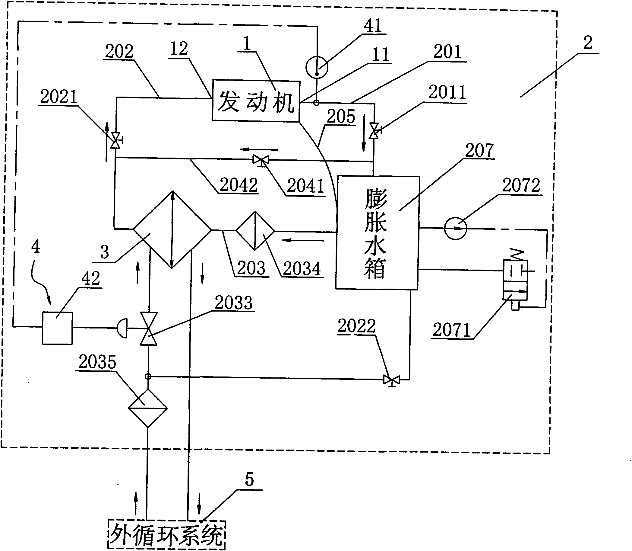
[0055] The cooling liquid described in the present invention may be water or other cooling liquids. In this embodiment, water or cooling liquid circulates in the internal circulation system, and water circulates in the external circulation system, but this is not limited thereto. The external circulation system of the present invention is a prior art, and will not be described in detail here. The internal circulation system of the present invention will be described in detail below.

[0056] During the engine test process, it is often necessary to simulate the vehicle condition and various complex test conditions for test control. Engine circulating water control is of great significance in engine testing, which directly ensures whether the engine can be tested and operated normally. The conventional circulating water temper...


PUM


Abstract

The invention relates to a cooling fluid temperature control system for testing engine performance. The cooling fluid temperature control system comprises a cooling fluid internal recycling system, a heat exchange device, a temperature monitoring and controlling device and a cooling fluid external recycling system, wherein the cooling fluid internal recycling system and the cooling fluid external recycling system are connected with the heat exchange device respectively; the cooling fluid internal recycling system is connected with an engine; the temperature monitoring and controlling device is connected with the cooling fluid internal recycling system, the heat exchange device and the cooling fluid external recycling system respectively; and the cooling fluid internal recycling system is a closed internal recycling system. A gas exhausting pipe is arranged on the conventional water temperature control system and communicates a cylinder cover water channel of the engine with a swelling water tank to ensure that the recycling water channel of the engine normally exhausts the gas; and the water inlet end and the water outlet end of the engine are additionally provided with bypass pipes and bypass valves to use water outlet pressure to compensate water inlet pressure so as to further reduce the difference of the water inlet pressure and the water outlet pressure, improve water inlet flow and water outlet flow and fulfill the aim that a cooling water system for engine tests simulates the operational states of the whole vehicle.

Description

technical field [0001] The invention relates to an engine performance testing device, in particular to a coolant temperature control system for engine performance testing. Background technique [0002] In order to ensure the normal operation of the engine in the test, the circulating water system is of great significance. The conventional circulating water temperature control method is an open cycle (that is, after the circulating water flows out of the engine water pump, it is exchanged and cooled by the radiator before entering the engine), that is, after the engine water pump drives the coolant to flow out of the engine, it is cooled by the radiator heat exchange. before returning to the engine, see figure 1 . Although this method can achieve the purpose of controlling the cooling of the engine, it cannot effectively control the water pressure, and when the temperature of the coolant is controlled at a boiling point of about 100°C, a large amount of water vapor will be ...

Claims


Application Information

Patent Timeline
Patent Type & Authority Applications(China)
IPC IPC(8): G01M15/02
CPCG01M15/02
Inventor 贾盛军尹伟王鹏
Owner BEIQI FOTON MOTOR CO LTD
Why Eureka
Try Eureka