
Light merging device

A technology of optical devices and beams, applied in optics, optical components, instruments, etc., to improve imaging quality, reduce shadow width, and improve imaging quality

Inactive Publication Date: 2011-02-09
YOUNG OPTICS KUSN
View PDF0 Cites 0 Cited by
  • Summary
  • Abstract
  • Description
  • Claims
  • Application Information

AI Technical Summary

Problems solved by technology

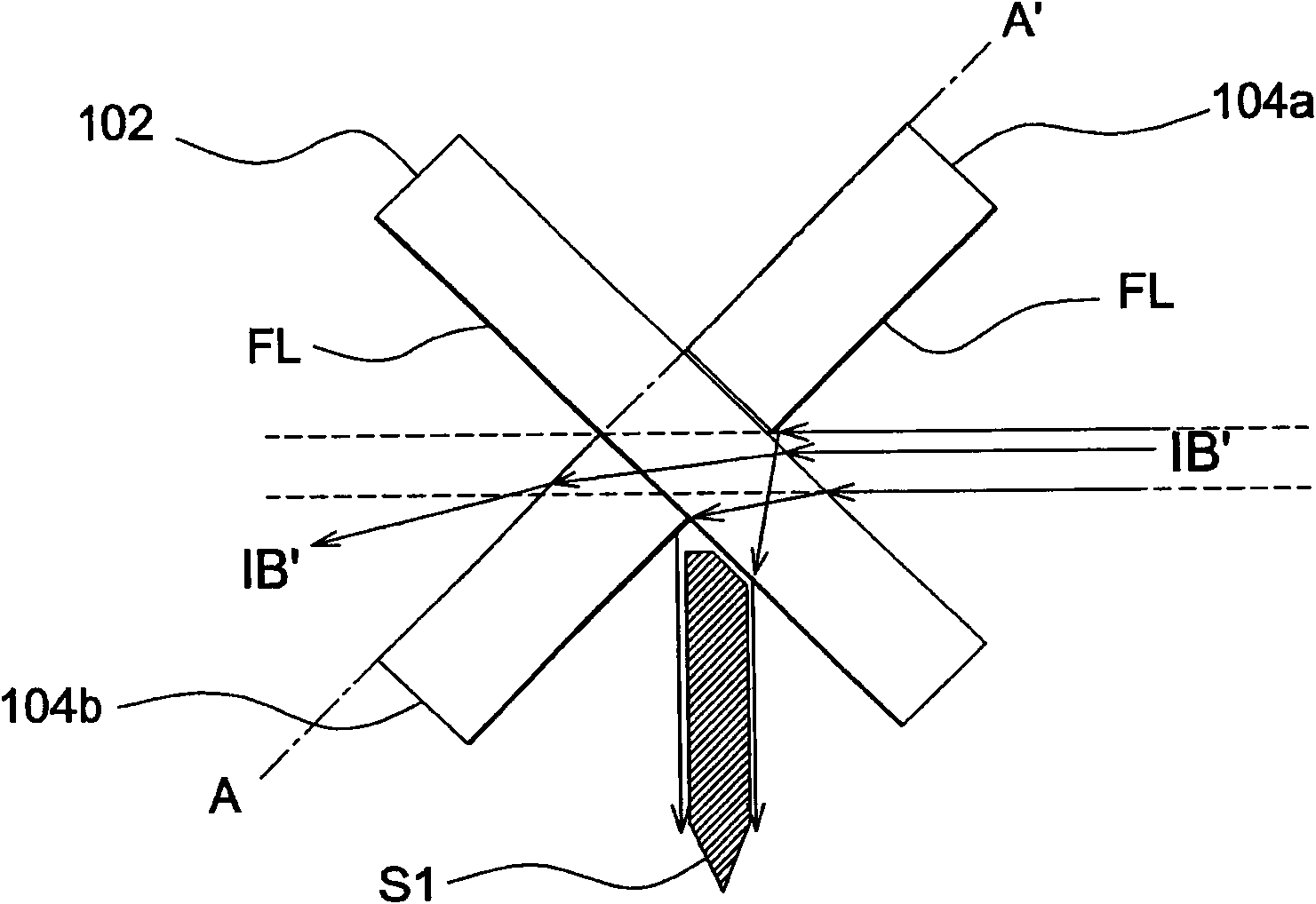
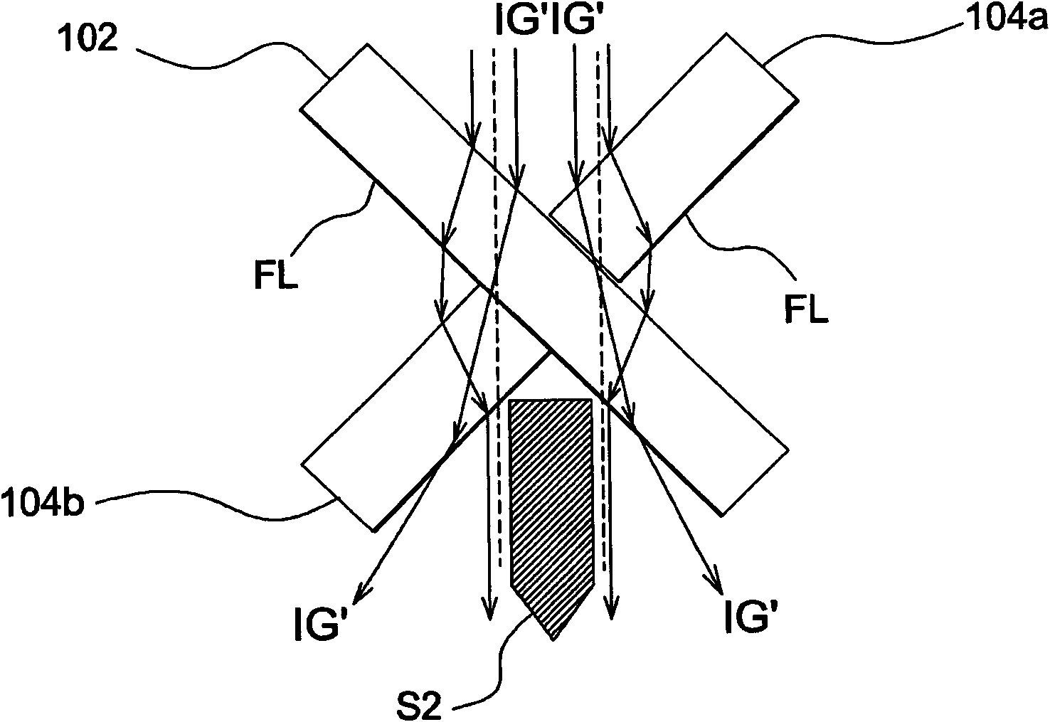
On the other hand, even if the dichroic mirror's dichroic coating FL is moved to the other side, the same shadow area is still produced

Method used


Image

  • Light merging device
  • Light merging device
  • Light merging device

Examples


Embodiment Construction

[0039] The aforementioned and other technical contents, features and effects of the present invention will be clearly presented in the following detailed description of the embodiments with reference to the drawings. The directional terms mentioned in the following embodiments, such as: up, down, left, right, front or back, etc., are only directions referring to the attached drawings. Accordingly, the directional terms are used to illustrate and not to limit the invention.

[0040] Figure 6 It is a schematic diagram of a light combining device 10 according to an embodiment of the present invention. Such as Figure 6 As shown, the light combination device 10 includes a first dichroic mirror 12 , a second dichroic mirror 14 and a third dichroic mirror 16 . The first dichroic mirror 12 can make the light beam in the first wavelength range penetrate and reflect the light beam outside the range, and the second dichroic mirror 14 and the third dichroic mirror 16 can make the lig...


PUM


Abstract

The invention relates to a light merging device which comprises a first color selective mirror, a second color selective mirror and a third color selective mirror, wherein the second color selective mirror is arranged on a first side of the first color selective mirror and forms an included angle with the first color selective mirror, the third color selective mirror is arranged on a second side of the first color selective mirror, the second side of the first color selective mirror faces back to the second color selective mirror, and the third color selective mirror is approximately parallel to the second color selective mirror. The second color selective mirror and the third color selective mirror are mutually staggered for a distance along the first color selective mirror.

Description

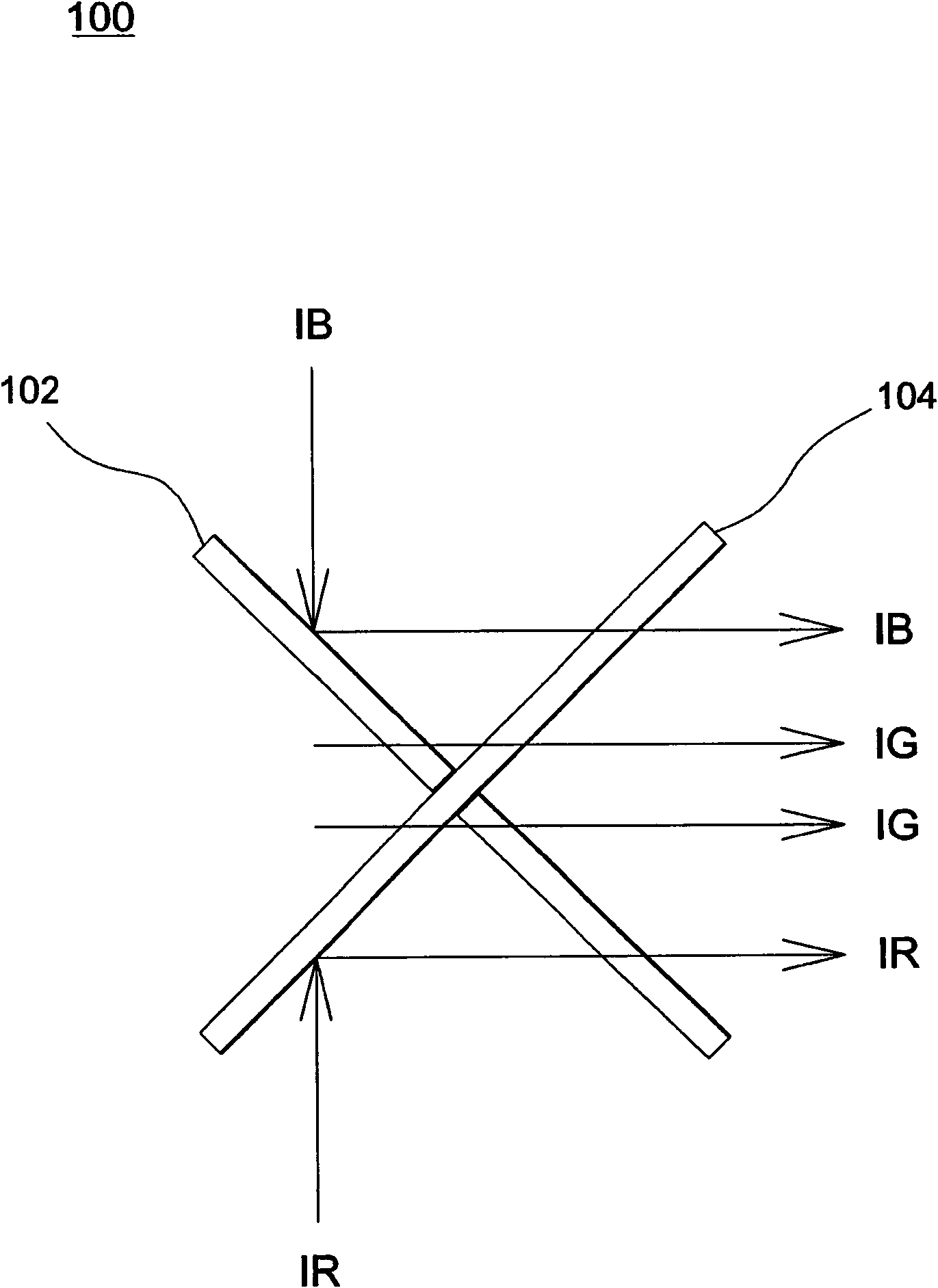
【Technical field】 [0001] The present invention relates to a light combining device, and more particularly to a light combining device with a dichroic mirror. 【Background technique】 [0002] figure 1 It is a schematic diagram showing a conventional light combining device 100 . Such as figure 1 As shown, the light combining device 100 includes a first dichroic mirror 102 (dichroic mirror) and a second dichroic mirror 104 arranged crosswise. The blue light IB can be reflected by the first dichroic mirror 102 and pass through the second dichroic mirror 104, the red light IR can be reflected by the second dichroic mirror 104 and pass through the first dichroic mirror 102, and the green light IG can pass through the first dichroic mirror 102. The color mirror 102 and the second dichroic mirror 104 can achieve the effect of turning the color light from different directions to be output along the same direction. [0003] please refer again figure 2 The enlarged schematic diagr...

Claims


Application Information

Patent Timeline
Patent Type & Authority Applications(China)
IPC IPC(8): G02B27/12G02B27/10
Inventor 蔡樟谙薛梅戴殷杰
Owner YOUNG OPTICS KUSN
Learn More