
Evaporation plating device

A technology of evaporation and evaporation materials, which is applied in the directions of vacuum evaporation plating, sputtering plating, ion implantation plating, etc., can solve the problems of pixel color mixing, color shift, etc., and achieve the goal of reducing shadow areas and improving uniformity Effect

Pending Publication Date: 2021-09-17
SHANGHAI SHINSEE OPTOELECTRONICS TECH CO LTD
View PDF0 Cites 0 Cited by
  • Summary
  • Abstract
  • Description
  • Claims
  • Application Information

AI Technical Summary

Problems solved by technology

In the evaporation process, the evaporation mask is used to cover the substrate, and the evaporation material is evaporated from the opening of the evaporation mask to the corresponding substrate position. However, due to the use of point source and line source, the evaporation source and the substrate There will be relative movement between the materials, which will cause the vapor deposition shadow area to appear in the gap between the mask and the substrate. If the shadow area is too large, it will cause color mixing and color shift of the pixels.

Method used


Image

  • Evaporation plating device
  • Evaporation plating device
  • Evaporation plating device

Examples


Embodiment Construction

[0048] The present application will be described in detail below in conjunction with the accompanying drawings and embodiments. It should be understood that the specific embodiments described here are only used to explain the present application, and are not intended to limit the present application.

[0049] In the description of the embodiments of this application, unless otherwise specified and limited, the terms "first" and "second" are only used for the purpose of description, and cannot be understood as indicating or implying relative importance; unless otherwise specified Or to explain, the term "plurality" refers to two or more; the terms "connection", "fixation" and so on should be understood in a broad sense, for example, "connection" can be a fixed connection or a detachable connection, or Connected integrally, or electrically; either directly or indirectly through an intermediary. Those of ordinary skill in the art can understand the specific meanings of the above...


PUM


Abstract

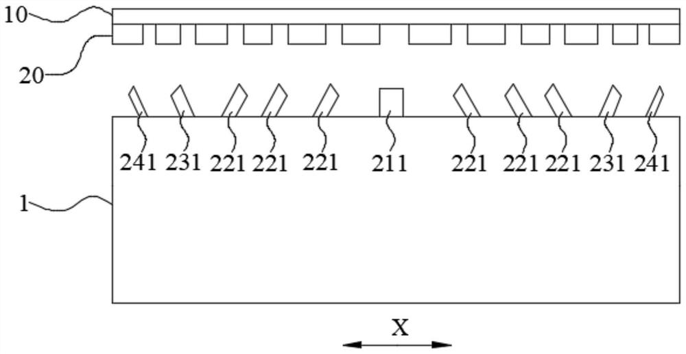
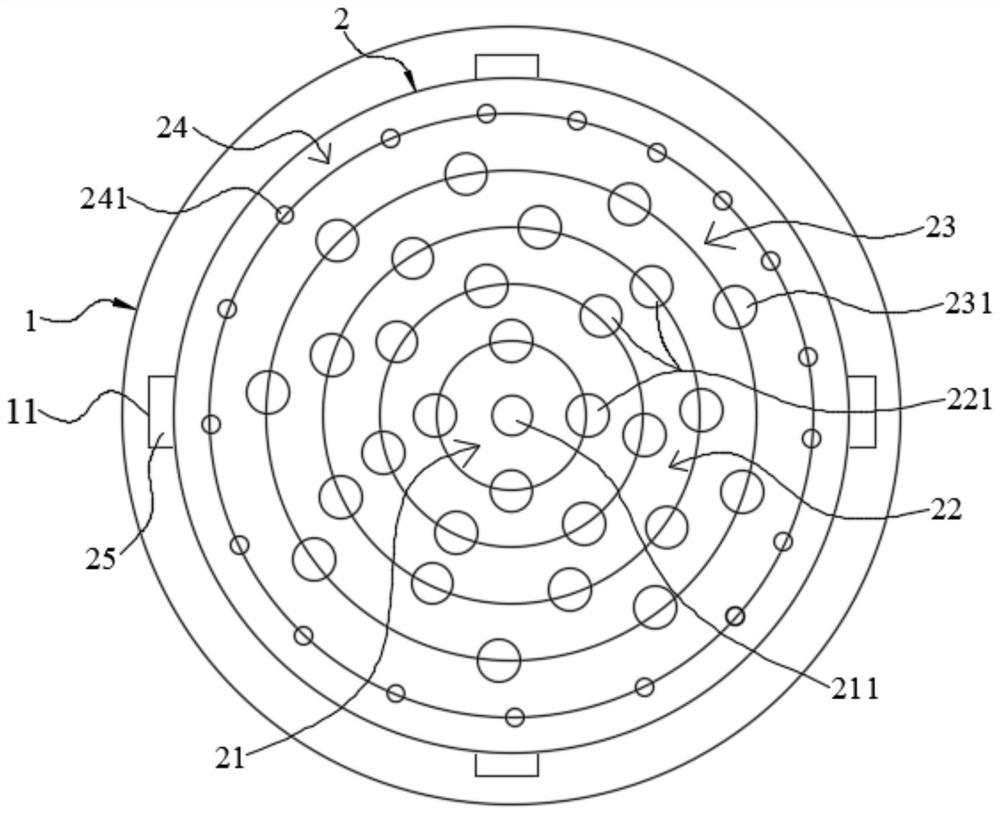
The invention relates to the technical field of evaporation plating, in particular to an evaporation plating device. The evaporation plating device comprises a crucible and a cover plate, wherein the cover plate is sequentially provided with a first area, a second area and a third area from inside to outside in the radial direction of the cover plate; the first area is provided with a first evaporation opening part which is concentric with the cover plate; the second area is provided with at least three circles of second evaporation opening parts which are distributed at equal intervals, the distances from the circle centers of the second evaporation opening parts in each circle to the circle center of the cover plate are equal, the distances between every two adjacent second evaporation opening parts in each circle are equal, and the connecting lines from the circle centers of the second evaporation opening parts in every two adjacent circles to the circle center of the cover plate do not coincide; and the third area is provided with at least one circle of a plurality of third evaporation opening parts which are distributed at equal intervals, the distances from the circle centers of the third evaporation opening parts in each circle to the circle center of the cover plate are equal, and the distances between every two adjacent third evaporation opening parts in each circle are equal. According to the evaporation plating device, the evaporation plating shadow area is effectively reduced, and the uniformity of the forming thickness of an evaporation plating material is improved.

Description

technical field [0001] The present application relates to the technical field of evaporation, and in particular to an evaporation device. Background technique [0002] In the OLED panel preparation process, the evaporation process is a key process. In the evaporation process, the evaporation mask is used to cover the substrate, and the evaporation material is evaporated from the opening of the evaporation mask to the corresponding substrate position. However, due to the use of point source and line source, the evaporation source and the substrate There will be relative movement between the materials, which will cause evaporation shadow areas in the gap between the mask and the substrate. If the shadow area is too large, it will cause color mixing and color shift of pixels. [0003] Therefore, there is an urgent need for an evaporation device to solve the above problems. Contents of the invention [0004] The present application provides an evaporation device to reduce th...

Claims


Application Information

Patent Timeline
IPC IPC(8): C23C14/24C23C14/04C23C14/12
CPCC23C14/243C23C14/042C23C14/12
Inventor 林文晶轩景泉刘萍
Owner SHANGHAI SHINSEE OPTOELECTRONICS TECH CO LTD
Learn More