
Sedimentary source

A technology of deposition source and deposition angle, applied in the field of deposition source, can solve problems such as multi-shadow areas

Active Publication Date: 2018-02-27
SAMSUNG DISPLAY CO LTD
View PDF9 Cites 0 Cited by
  • Summary
  • Abstract
  • Description
  • Claims
  • Application Information

AI Technical Summary

Problems solved by technology

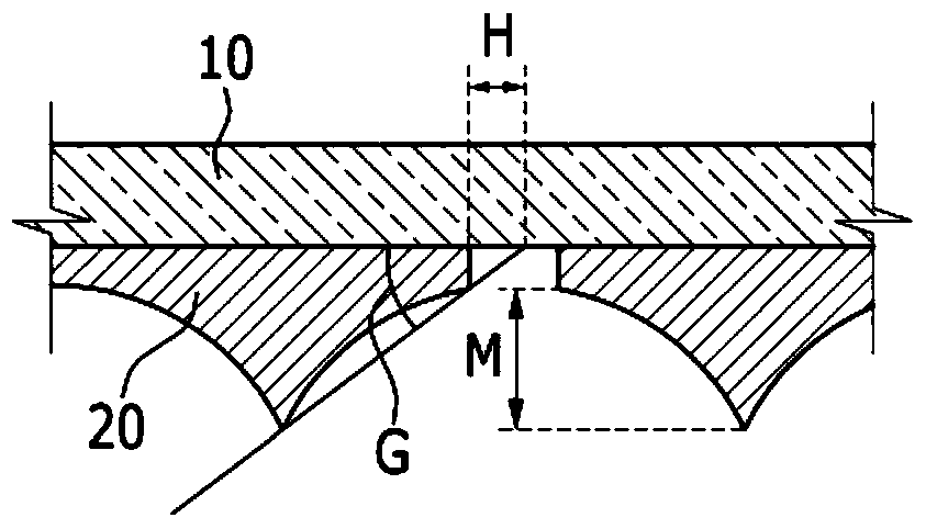
As a result, the mask is not in contact with the substrate, creating excessive shadow areas

Method used


Image

  • Sedimentary source
  • Sedimentary source
  • Sedimentary source

Examples


Embodiment Construction

[0029] The invention will be understood more fully hereinafter with reference to the accompanying drawings, in which embodiments of the invention are shown. The described embodiments may be modified in various different ways, all without departing from the spirit or scope of the present invention. Components having the same configuration in the embodiments will be described using the same reference numerals as in the first embodiment and can be used to refer to the same parts in all the embodiments, the first embodiment will be described and in the other embodiments Only parts different from those of the first embodiment are explained in .

[0030] In order to clearly describe the present invention, parts irrelevant to the description are omitted, and the same reference numerals are used to refer to the same or similar parts throughout the specification.

[0031] In the specification and claims, when it is described that an element is "coupled" to another element, it not only...


PUM


Abstract

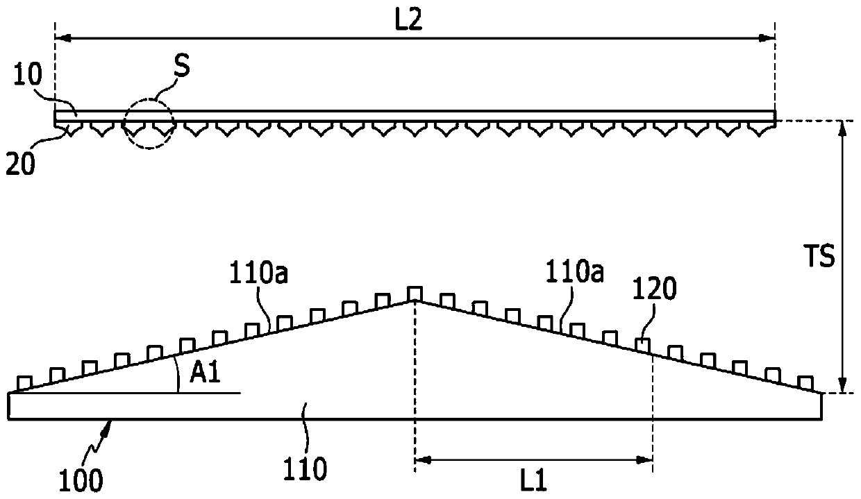
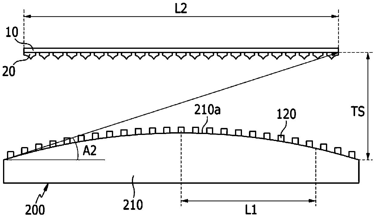
The deposition source includes the main body and multiple nozzles, where the subject has a predetermined length, which is formed on the subject and emitted the sedimentary material to the substrate with a mask.The subject is formed to make the part of the subject from the center of the subject, the distance between the subject and the substrate gradually increases, orTo the relative end of the subject, the distance between the nozzle and the substrate gradually increases, thereby reducing the shadow area caused by the sedimentary material when the sedimentary material is deposited on the substrate.

Description

technical field [0001] The present disclosure relates to deposition sources. Background technique [0002] An organic light emitting diode (OLED) display exhibits a color according to light emission caused by recombination of holes and electrons injected into an anode and a cathode in an emission layer, and has a laminated structure including an emission layer between an anode and a cathode. However, it is difficult to obtain high-efficiency light emission through the above-mentioned structure, so interlayers such as electron injection layer (EIL), electron transport layer (ETL), hole transport layer (HTL) and hole injection layer (HIL) are selectively located in each between the electrons and the emissive layer. [0003] Interlayers of electrons and emissive layers including OLED displays can be formed by various methods including deposition. In order to manufacture an OLED by using deposition, a mask having the same pattern as a thin film to be formed on a substrate is a...

Claims


Application Information

Patent Timeline
Patent Type & Authority Patents(China)
IPC IPC(8): C23C14/24C23C14/04
CPCC23C14/042C23C14/24
Inventor 洪宰敏朴峻永
Owner SAMSUNG DISPLAY CO LTD
Learn More