Brake system for a vehicle

A technology for braking equipment and automobiles, which is applied in the direction of brakes, braking transmissions, and vehicle components, and can solve problems such as high installation costs and expensive manufacturing of braking equipment, and achieve fewer components, lower installation costs, and save effect of space

Inactive Publication Date: 2011-02-09
WABCO GMBH
View PDF4 Cites 16 Cited by
  • Summary
  • Abstract
  • Description
  • Claims
  • Application Information

AI Technical Summary

Problems solved by technology

Furthermore, in the known arrangements, the installation outlay and thus the install

Method used


Image

  • Brake system for a vehicle
  • Brake system for a vehicle
  • Brake system for a vehicle

Examples


Embodiment Construction

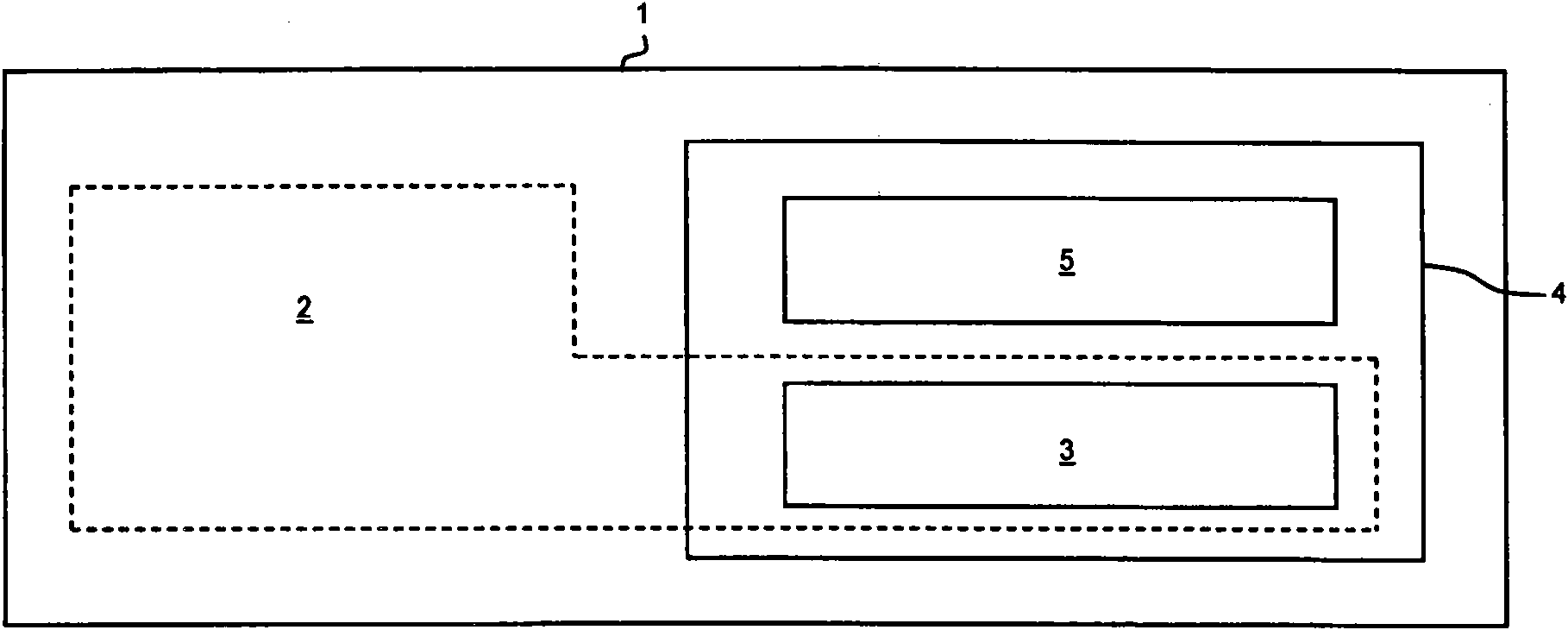
[0046] figure 1 A block diagram of the brake system 1 is shown. The brake system 1 has a parking brake function 2 . The parking brake function 2 includes a parking brake control function 3 . Furthermore, the brake system 1 has a device 4 . This device 4 has a second function 5 which differs from the parking brake function 2 . According to the invention, the parking brake control function 3 is arranged together with the second function 5 in a device 4 of the brake system 1 .

[0047] The device 4 with the second function 5 is in this case the electronic and / or electro-pneumatic device of the brake system 1 . Device 4 is, for example, an air preparation device, an axle regulator, a trailer control valve, a control device for an electronic brake system or a driving dynamics control device.

[0048] on the basis figure 1 Alternatively to this exemplary embodiment of the present invention, the device 4 with the parking brake control function 3 and the second function 5 can be...


PUM


Abstract

The invention relates to a brake system (1) for a vehicle. Said brake system (1) has a parking brake function (2) for immobilizing said vehicle. Said parking brake function (2) in turn has a parking brake control function (3) for the electronic control of the immobilization. Furthermore, an electronic and/or electropneumatic device (4, 6, 14, 26, 34, 162, 179, 186, 208, 210) of the brake system (1), particularly an air treatment device (26, 162, 179, 186, 208), an axle modulator (34), a trailer control valve, a controller of an electronic brake system, or a driving dynamics regulating unit (210), and/or an electropneumatic device of the vehicle, particularly an air treatment device or an air suspension device, have a second function (5). Said second function (5) differs from the parking brake function (2). According to the invention, in addition to the second function (5) said device (4, 6, 14, 26, 34, 162, 179, 186, 208, 210) has the parking brake control function (3).

Description

technical field [0001] The invention relates to a brake system of a motor vehicle, in particular a commercial vehicle, which has a parking brake function. The main task of the parking brake function is to park the vehicle and thus prevent unintentional rolling. The parking brake function includes a parking brake control function that electronically controls the parking of the vehicle. Background technique [0002] Furthermore, such a brake system has a device with a second function different from the parking brake function. The device can be assigned to the brake system or to the vehicle. In the case of an associated brake system, the device is an electronic and / or electro-pneumatic device of the brake system. The device can be, in particular, an air preparation device, an axle regulator, a trailer control valve, a control device for an electronic braking system or a driving dynamics control device. Additionally or alternatively, the device can be assigned to the vehicle...

Claims


Application Information

Patent Timeline
IPC IPC(8): B60T13/66
CPCB60T13/662B60T13/04B60T13/588B60T13/683
Inventor 乌韦·本施盖伊·阿兰·吉奥楚昂吉亚亨宁·弗尔斯特马蒂亚斯·格里姆奥拉夫·扬茨伯恩德-约阿希姆·基尔维尔弗里德·门策哈特穆特·罗森达尔安德烈亚斯·舍勒沃尔夫冈·施特拉赫奥特马尔·施特鲁韦
Owner WABCO GMBH
Why Eureka
Try Eureka