Dual force ram drive for a screw press

A driving device and screw-driven technology, applied in the direction of presses, punching machines, manufacturing tools, etc., can solve the problems of high cost, large physical size, and high power.

Inactive Publication Date: 2011-02-09
PEM MANAGEMENT INC
View PDF8 Cites 2 Cited by
  • Summary
  • Abstract
  • Description
  • Claims
  • Application Information

AI Technical Summary

Problems solved by technology

Achieving these characteristics using a single driver unit is impractical due to cost, power and physical size constraints

Method used


Image

  • Dual force ram drive for a screw press
  • Dual force ram drive for a screw press
  • Dual force ram drive for a screw press

Examples


Embodiment Construction

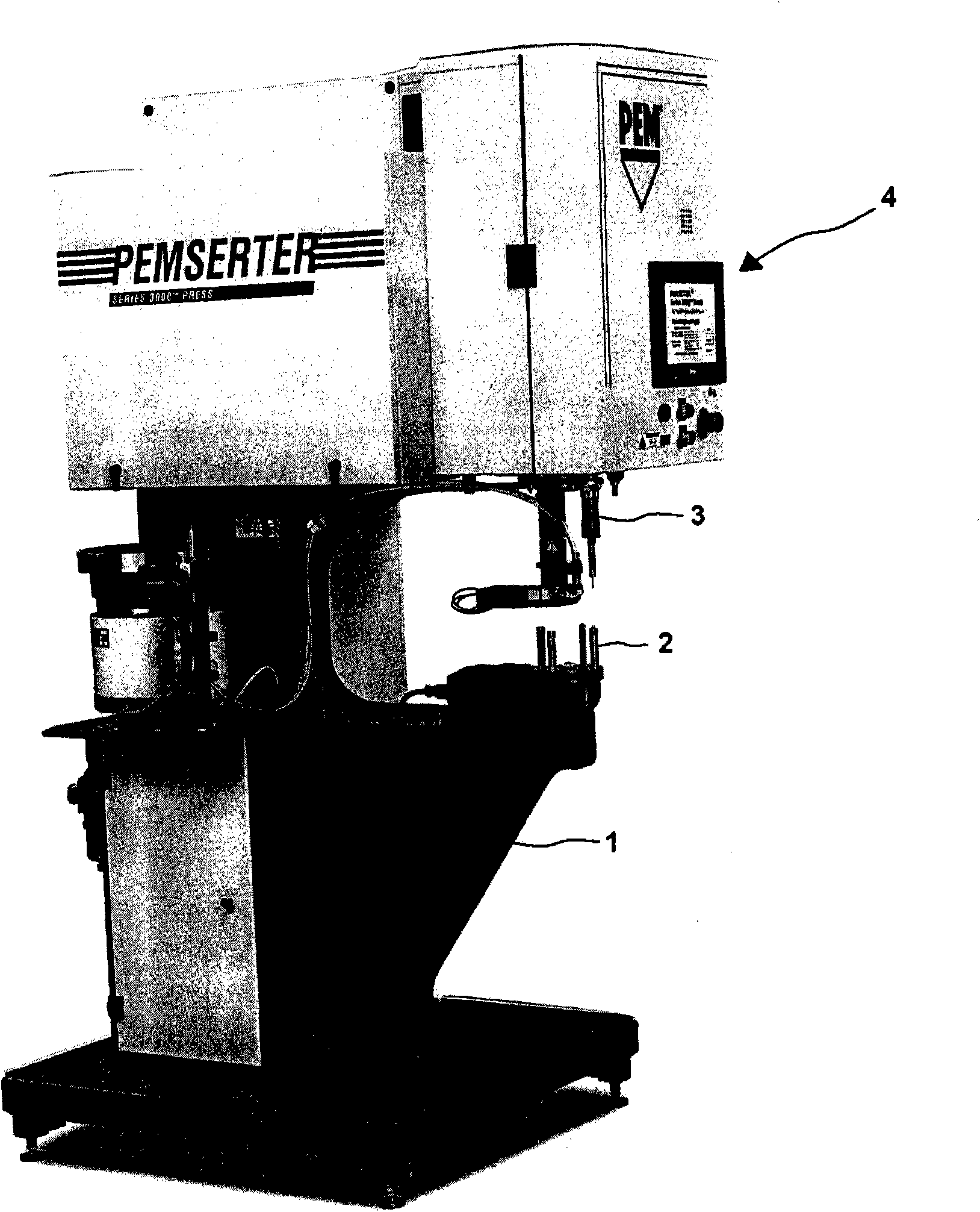
[0015] now refer to figure 1 , shows a punching machine 4 embodying the invention comprising a C-shaped frame 1 supporting an anvil 2 reciprocally impacted by a ram 3 .

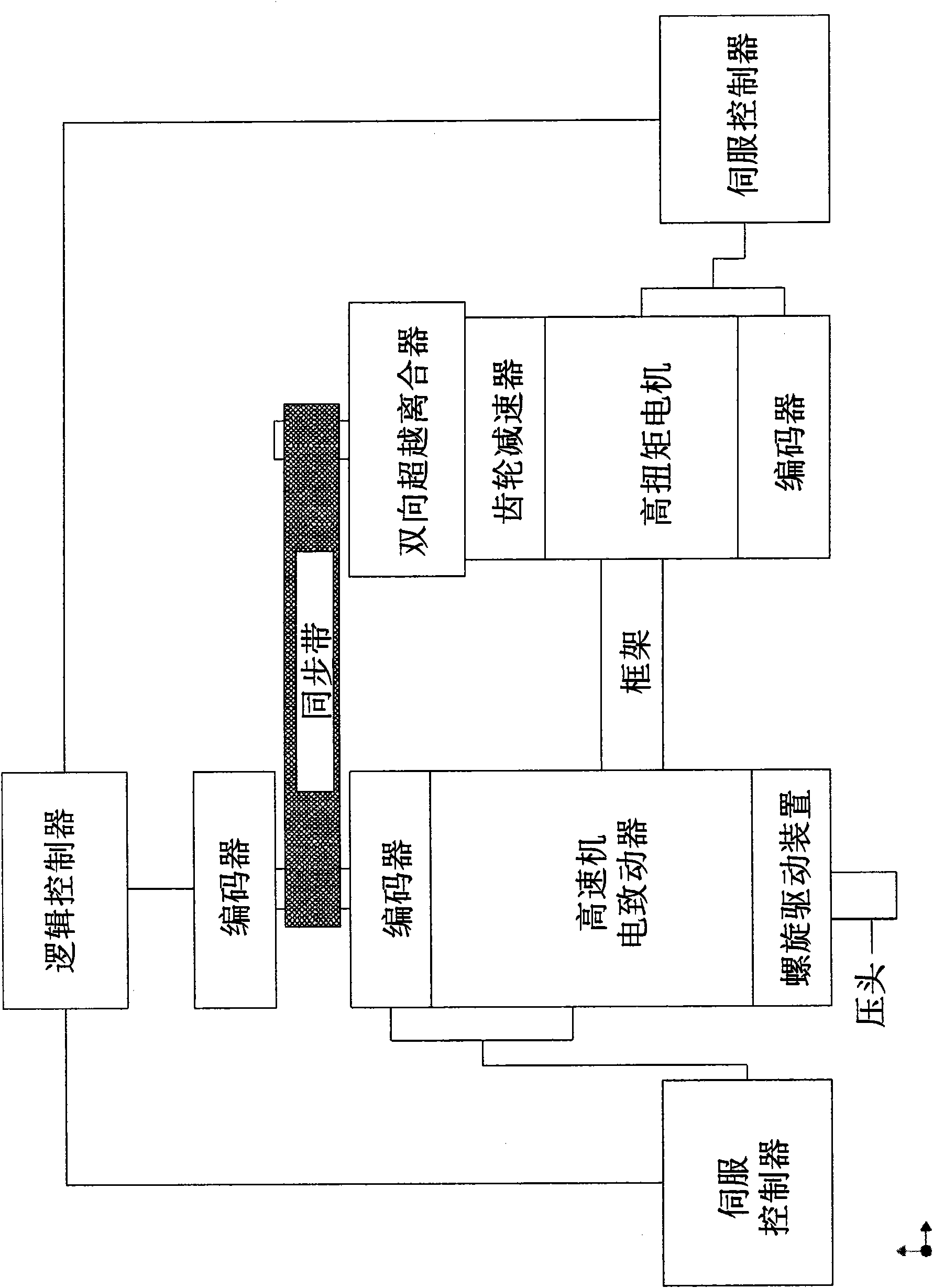
[0016] now refer to figure 2 , which discloses the main components of the invention, including a frame for supporting the basic mechanical components of the invention, including high-speed mechanical drives and high-torque motors. The frame also supports a screw drive which can be operated in both directions by high speed or low speed motor means. A bi-directional self-disengaging clutch is connected to a high torque motor unit which includes a motor / gear reducer combination. The programmable logic controller regulates the operation of the two motors through the screw drive device, thereby regulating the movement of the ram. The two-way clutch is connected to the main shaft of the screw drive via a timing belt. The logic controller regulates the movement of the ram according to a stamping profile, which ...


PUM


Abstract

Precise motion of the ram of a fastener press is controlled by high torque and low torque motors for high speed / low force and high force pressing of the ram by the ram, respectively. The high torque motor means drive passes through a bidirectional overrunning clutch. The clutch is controlled by the relative motion of the two separate motor drive speeds of which are regulated by a controller. The clutching motion is therefore controlled only by the relative speed of its drive versus driven components. This provides an extremely smooth and responsive transition between high speed / low force and low speed / high force operation of the ram so that the pressing cycle can be as fast and efficient as possible.

Description

[0001] related application [0002] This patent application is related to Provisional Patent Application Serial No. 60 / 972,436, filed September 14, 2007, entitled "Setting System for Fastener Presses," and the invention, filed September 14, 2007, Provisional Patent Application Serial No. 60 / 972,447, entitled "Dual Force Ram Drive for Screw Presses," which is hereby claimed as priority. technical field [0003] This invention relates to fastener presses that utilize servo motors to precisely control the position of the ram. More specifically, the present invention relates to a servo motor driven ram having independent strong and weak drive motors using a clutch type drive mechanism and regulated by a controller. Background technique [0004] Desirable characteristics of a fastener press are high speed and high force. Achieving these characteristics using a single driver unit is impractical due to the constraints of high cost, high power, and large physical size. However, a...

Claims


Application Information

Patent Timeline
Patent Type & Authority Applications(China)
IPC IPC(8): B60W10/02
CPCB30B1/186B30B1/18B30B15/12
Inventor R·B·帕顿
Owner PEM MANAGEMENT INC
Why Eureka
Try Eureka