Cylinder beam integrated hydraulic press

An integrated, hydraulic press technology, applied in the field of hydraulic press and cylinder beam integrated hydraulic press, can solve the problems of weakening of the upper beam rigidity and strength of the working cylinder hole, easy loosening of the threaded connection, and high quality of the whole machine, and achieves low manufacturing cost and high structure. Solid, lightweight effect

Active Publication Date: 2012-12-26
HARBIN INST OF TECH
View PDF0 Cites 0 Cited by
  • Summary
  • Abstract
  • Description
  • Claims
  • Application Information

AI Technical Summary

Problems solved by technology

[0003] The purpose of the present invention is to solve the problems that the rigidity and strength of the upper beam of the existing three-beam four-column hydraulic press are weakened by the working cylinder hole, the threaded connection between the upper beam and the lower beam and the column is easy to loose, the quality of the whole machine is large and the cost is high. A cylinder-beam integrated hydraulic press is provided

Method used


Image

  • Cylinder beam integrated hydraulic press
  • Cylinder beam integrated hydraulic press
  • Cylinder beam integrated hydraulic press

Examples


specific Embodiment approach 1

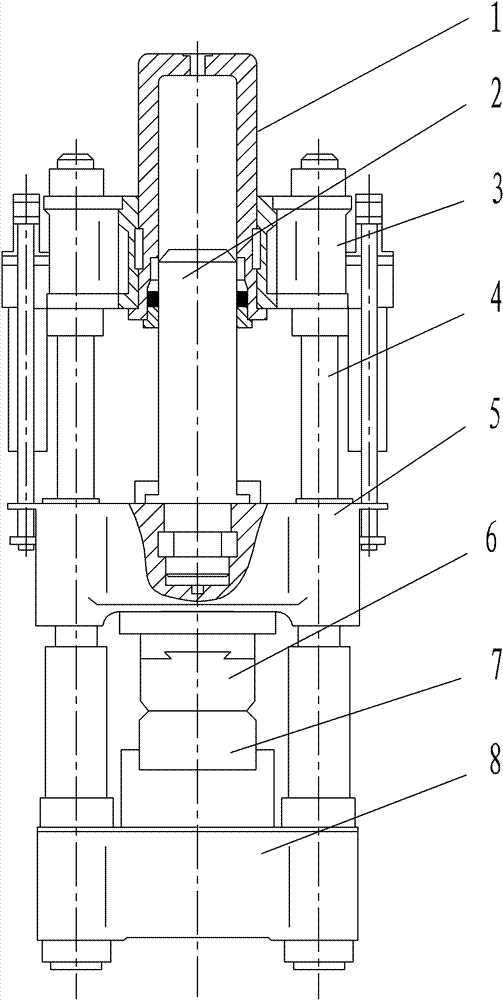
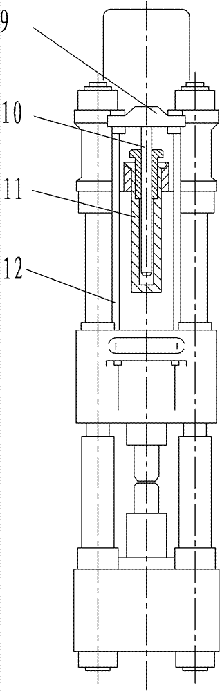
[0008] Specific implementation mode one: combine Figure 3-Figure 5 To illustrate this embodiment, the cylinder-beam integrated hydraulic press of this embodiment includes an upper die 6, a lower die 7, a workbench 15 and two return cylinders 11, and the hydraulic press also includes a housing 13, a slider 14, and a thrust plunger 16 , a sealed guide sleeve 18, a cage 20, a fixed plate 19, two guide sleeves 22, two guide posts 23 and a plurality of legs 27, the inner wall of the housing 13 is fixedly equipped with a cage 20, the cage 20 is fixed with a sealed guide sleeve 18, the thrust plunger 16 is set in the sealed guide sleeve 18, and moves up and down in the sealed guide sleeve 18, the cage 20, thrust plunger 16, belt The sealed guide sleeve 18 and the upper part of the housing 13 form a high-pressure fluid chamber 21, and the lower end surface of the thrust plunger 16 is provided with a slider 14, the slider 14 is an inverted concave slider, and the upper mold 6 is fixed...

specific Embodiment approach 2

[0009] Specific implementation mode two: combination image 3 and Figure 4 The present embodiment will be described. The casing 13 of the present embodiment has a thickness smaller than 1 / 40 of its outer diameter. With such arrangement, the quality of the hydraulic press is lighter. Other compositions and connections are the same as in the first embodiment.

specific Embodiment approach 3

[0010] Specific implementation mode three: combination image 3 and Figure 4 Describe this embodiment, the housing 13 of this embodiment is composed of an upper housing 13 - 1 , a middle housing 13 - 2 , and a lower housing 13 - 3 which are sequentially fixedly connected from top to bottom. Such arrangement facilitates manufacture. Other compositions and connections are the same as those in Embodiment 1 or Embodiment 2.


PUM


Abstract

A hydraulic press with integrated cylinder and beam comprises a housing (13), a thrust plunger (16), a worktable (15), a sliding block (14), an upper die (6) and a lower die (7). A retainer (20) is fixedly installed on the inner wall of the housing. A guide sleeve (18) with a seal is fixedly installed in the retainer. The thrust plunger is disposed in the guide sleeve and is movable up and down. The lower end of the thrust plunger is connected with the sliding block (14). The upper die is fixedly installed on the bottom end surface of a groove of the sliding block. A fixing plate (19) is installed and fixed horizontally in the housing. The worktable is mounted on the fixing plate. The lower die is mounted on the worktable, and corresponds to the upper die. The hydraulic press is characterized by light weight, high total pressure and low cost.

Description

technical field [0001] The invention relates to a hydraulic machine, in particular to a cylinder-beam integrated hydraulic machine, which belongs to the technical field of hydraulic equipment. Background technique [0002] Hydraulic press is a general-purpose equipment, commonly used in sheet metal forming and bar forging in the fields of automobile manufacturing, aircraft manufacturing, shipbuilding and light industrial product manufacturing, as well as hot isostatic pressing and cold isostatic pressing of powder bodies and non- Metal laminate pressing and brick pressing. The traditional hydraulic press is a three-beam and four-column structure, such as figure 1 and figure 2 shown. The working cylinder 1 bears the high-pressure fluid, and the fluid pressure in it pushes the rod 2 to move downward. The working cylinder 1 passes through the inner hole in the middle of the upper beam 3 and is fixed in the upper beam 3 with a flange. There are four columns 4 for the movable...

Claims


Application Information

Patent Timeline
Patent Type & Authority Patents(China)
IPC IPC(8): B30B1/32B30B15/00
CPCB30B1/32B30B15/04
Inventor 王仲仁苑世剑王小松何祝斌
Owner HARBIN INST OF TECH
Why Eureka
Try Eureka