Moment and speed sensor of electric bicycle

A technology of electric bicycles and speed sensors, which is applied in the direction of instruments, torque measurement, vehicle components, etc., can solve the problems of complex structure, no output, easy winding of sensor lead wires, etc., and achieve good signal transmission stability and measurement sensitivity High, the effect of improving work performance and measurement accuracy

Active Publication Date: 2011-02-16
苏州同盛电器有限公司
View PDF8 Cites 19 Cited by
  • Summary
  • Abstract
  • Description
  • Claims
  • Application Information

AI Technical Summary

Problems solved by technology

However, although there are torque and speed sensors in China now, the effect is not satisfactory. The main reason is that the normal torque signal cannot be output at low speeds, causing the force at the start to be either too large or too small to achieve man-machine coordination. When riding hard, the output signal of the sensor is saturated too early, resulting in weak uphill, and the overall working stability and sensitivity are poor
Although foreign countries (especially Japan) have long had such products, their structures are complicated, their manufacturing difficulty and cost are high, and the lead wires of the sensors are easily wound on the central axis of the bicycle, so there is a gap between the rotating electrical signal and the static electrical signal. Conversion difficulties prevent this type of e-bike from becoming popular anytime soon

Method used


Image

  • Moment and speed sensor of electric bicycle
  • Moment and speed sensor of electric bicycle
  • Moment and speed sensor of electric bicycle

Examples


Embodiment

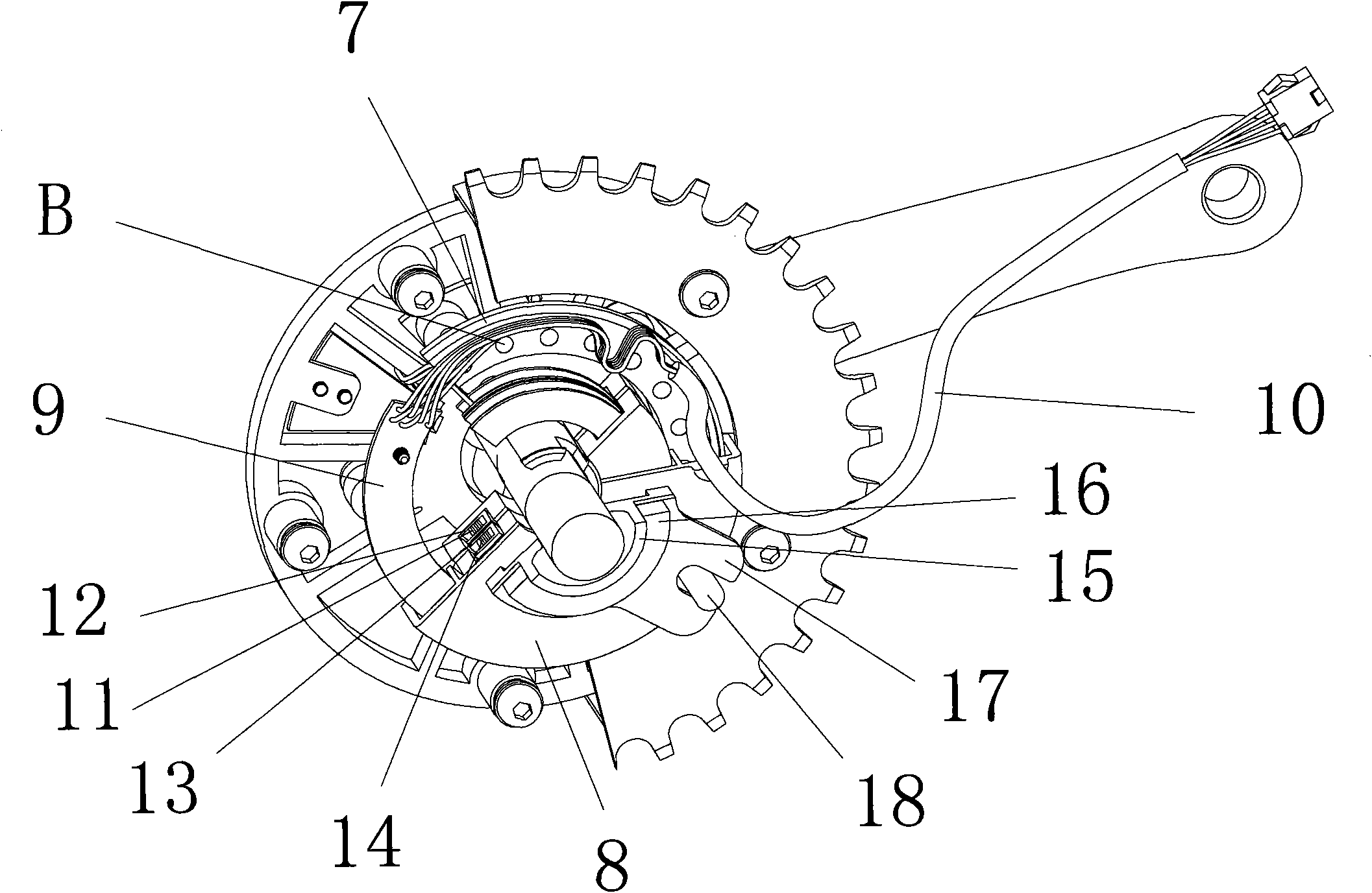
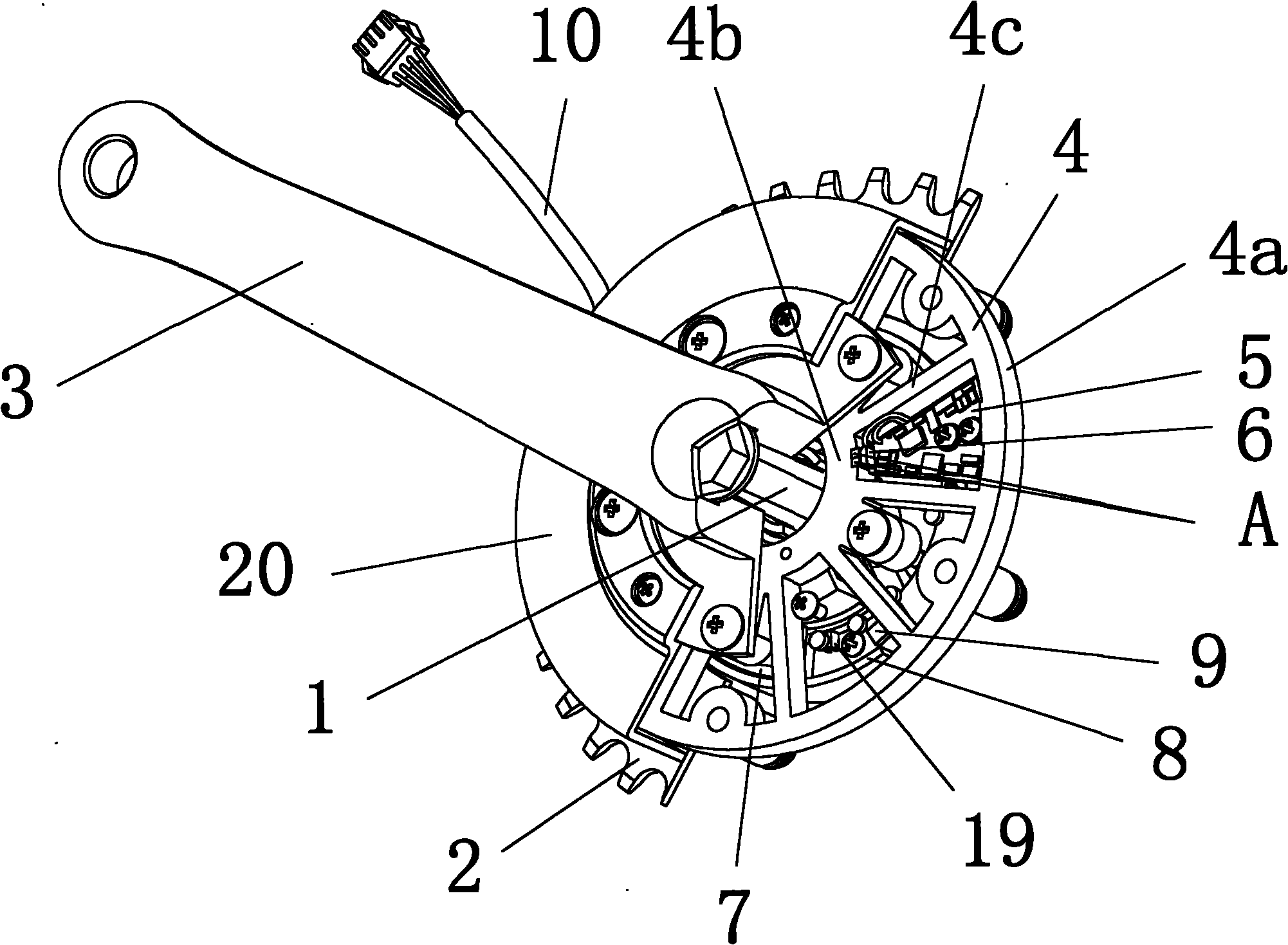
[0022] Example: Combine figure 1 , figure 2 As shown, the electric bicycle torque and speed sensor provided by the present embodiment consists of a central shaft 1, a tooth plate 2, a crank 3 fixed on the central shaft 1, a deformation frame 4, a signal output plate 5, a linear Hall element 6, Rotating part 7, stationary part 8, signal receiving plate 9, lead wire 10, rotating magnetic pot 11, rotating coil 12, stationary magnetic pot 13, stationary coil 14, central axis bowl 15, central joint 16, stop-rotating piece 17, stop The rotary rod 18, the switch Hall element 19 and the protective cover 20 are formed together.

[0023] In the present embodiment, the deformation frame 4 is composed of an outer ring 4a, an inner ring 4b and 10 connecting ribs 4c that are radially connected between the inner ring and the outer ring ( figure 1 Only half of the deformation frame 4) is shown in the figure, in which the inner ring 4b and the crank 3 are fastened by screws, and the outer r...


PUM


Abstract

The invention discloses a moment and speed sensor of an electric bicycle. The sensor comprises a middle shaft, a chain wheel, a crank and a deformation frame, wherein the crank is fixed to the middle shaft; the deformation frame comprises an outer ring and an inner ring which are connected by a plurality of radial connecting ribs; the inner ring is fastened on the crank and the outer ring is fastened on the chain wheel; two moment sensitive magnetic steels are fixed on the inner ring and the outer surfaces of the two moment sensitive magnetic steels have reverse polarities; a signal output board is fixed on the outer ring and a linear hall element is arranged on the signal output board; a sensitive surface of the linear hall element is opposite to the outer surfaces of the two magnetic steels; the sensor also comprises a rotating member and a static member which are coaxially sleeved on the middle shaft; a secondary winding is fixed on the rotating member; a primary winding and a signal receiving board are fixed on the static member; the primary winding and the secondary winding together form an isolating transformer; the primary winding is electrically connected with an alternating current generator arranged on the signal receiving board; the signal receiving board is provided with a lead-out wire; and the secondary winding is electrically connected with the signal output board. The sensor has high work stability and sensitivity.

Description

technical field [0001] The invention relates to a moment and speed sensor of an electric bicycle. Background technique [0002] Electric bicycles are being increasingly used in my country because of their brisk, labor-saving and pollution-free features. Traditional electric bicycles use handlebars to adjust the speed, and there are also so-called smart electric bicycles that use speed sensors to control the output power of the motor. The characteristics of this type of smart electric bicycle are that it is easy to ride on flat ground, but very laborious to go uphill . Electric bicycles using torque and speed sensors are just the opposite. When riding on flat ground, the output power of the motor is very small, which can make people feel easy to ride and save power, but it can output a larger current when going uphill. It saves effort to climb hills, and it is an electric bicycle that truly allows people to experience the natural integration of man and machine. However, al...

Claims


Application Information

Patent Timeline
Patent Type & Authority Applications(China)
IPC IPC(8): B62M6/50
CPCG01L3/1435B62M6/50
Inventor 马庆一
Owner 苏州同盛电器有限公司
Why Eureka
Try Eureka