Safety lock with rotary bolt

A technology of turning tongue and safety, which is applied in the direction of locks controlled by non-mechanical transmission, building locks, door/window accessories, etc. The problem of the large size of the tongue lock is to achieve the effect of convenient and effective management of door opening records and status, which is conducive to daily maintenance and stable and reliable work.

Inactive Publication Date: 2011-02-16
HEFEI TIANZHI TECH DEV
View PDF7 Cites 5 Cited by
  • Summary
  • Abstract
  • Description
  • Claims
  • Application Information

AI Technical Summary

Problems solved by technology

[0002] Existing electronic cam locks are usually larger in size and more expensive, which limits the widespread promotion of electronic cam locks in power systems; at the same time, the existing electronic cam locks have poor confidentiality and anti-theft performance, and it is difficult to meet customer requirements. needs to be improved

Method used


Image

  • Safety lock with rotary bolt
  • Safety lock with rotary bolt
  • Safety lock with rotary bolt

Examples


Embodiment 1

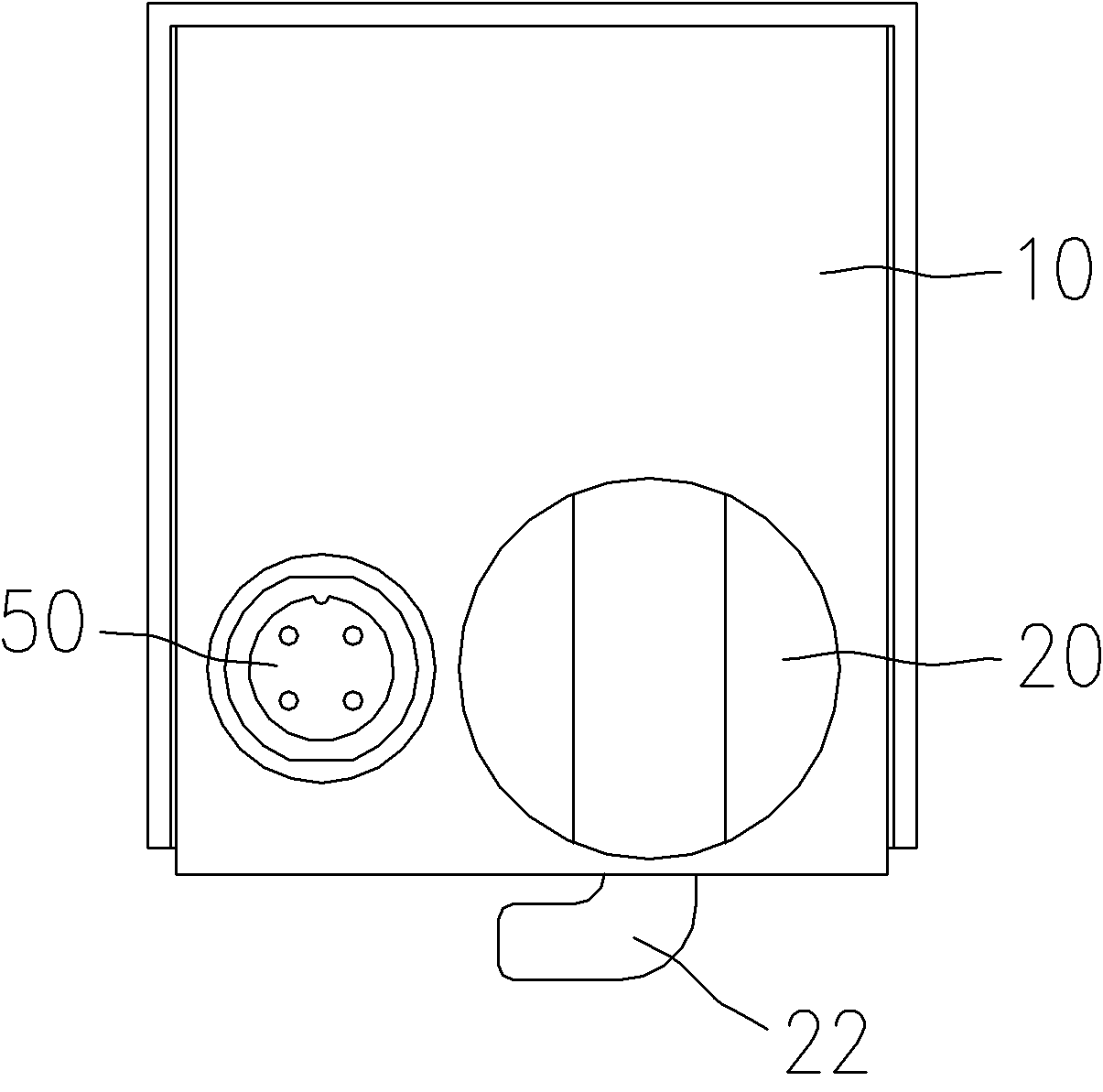
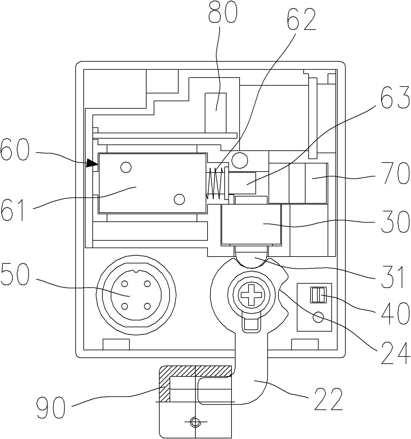
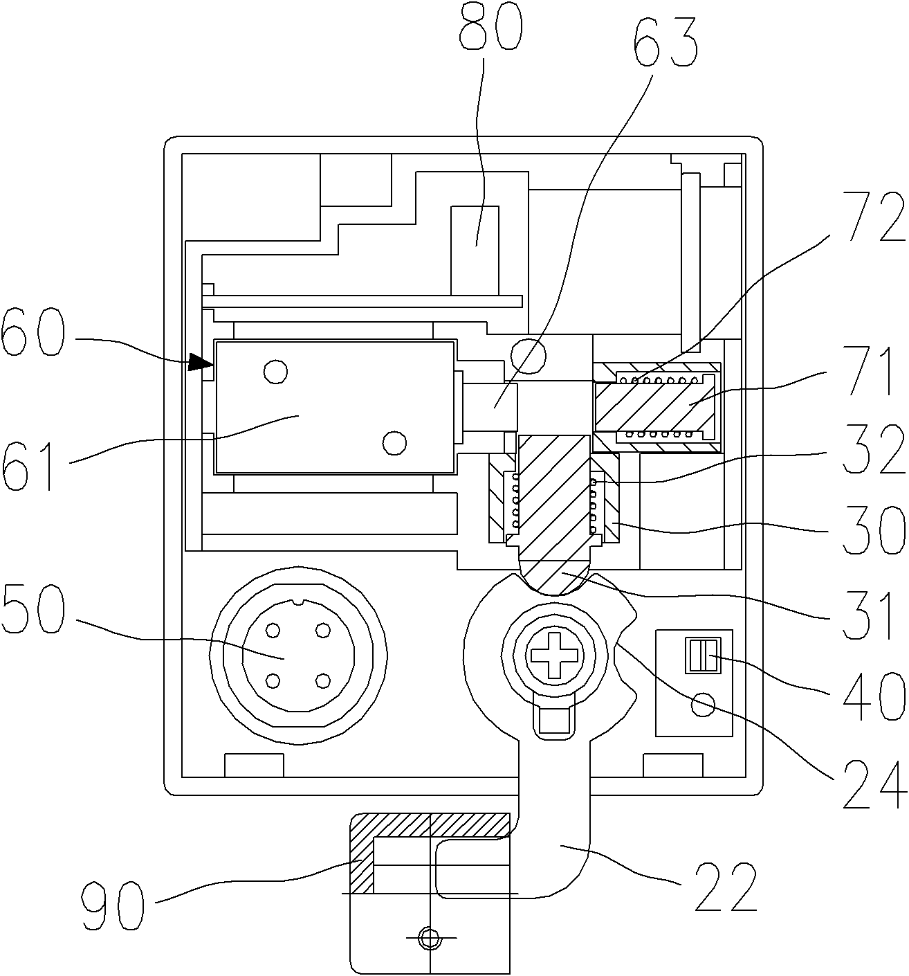
[0022] Embodiment 1: as Figure 2~4 As shown, the detection switch 40 is a photoelectric switch, and the photoelectric switch is arranged on the side of the lock plug mechanism. The turning tongue 22 is provided with a reflective light on the shaft extending from its disc-shaped end to the outside of the lock body 10. surface 25, the photoelectric switch is only matched with this reflective surface 25, and the reflective surface 25 is in a high position (i.e. Figure 2~4 horizontal position shown) or low (i.e. Figure 2~4 vertical position shown), and the light emitted by the photoelectric switch is reflected back to the photoelectric switch or absorbed by the surface of other objects in the lock body 10 except the reflective surface 25, so as to form a driving signal and pass through the photoelectric switch. The output end is connected to the input end of the control module 80, and the control module 80 controls the action of the electromagnetic clutch 60 and makes the shaf...

Embodiment 2

[0024] Embodiment 2: The detection switch 40 is an electronic device with a shrapnel, which is arranged on the side of the lock plug mechanism, and the rotary tongue 22 extends from its disc-shaped end to the outside of the lock body 10 There is a support arm on the shaft to cooperate with the shrapnel, and the support arm is in a high position (i.e. Figure 2~4 horizontal position shown) or low (i.e. Figure 2~4 The vertical position shown), when the arm is in the low position and the shrapnel abuts together so that the contacts in the electronic device are closed, when the arm is in the high position and the shrapnel is disengaged so that the contacts in the electronic device Opening, the opening or closing of the contact forms a drive signal and is connected to the input terminal of the control module 80 through the output terminal of the electronic device. The control module 80 controls the action of the electromagnetic clutch 60 and makes the annular convex part away from...


PUM


Abstract

The invention belongs to the field of electronic locks, and particularly relates to a safety lock with a rotary bolt. The safety lock comprises a handle arranged on a lock body; one end, positioned in the lock body, of the handle is fixedly provided with a lock pin; the other end of the lock pin is connected with one end of the rotary bolt positioned inside the lock body; the handle drives the lock pin and drives the rotary bolt to rotate around the fixed end of the rotary bolt; the interior of the lock body is also provided with a lock plug mechanism and an electronic locking mechanism; and the lock plug mechanism is matched with the electronic locking mechanism so that the rotary bolt is in two position states of locking and unlocking. The safety lock is convenient to unlock, reliable to lock and high in burglar-proof performance; the locking and unlocking processes of the safety lock are operated by a palm computer, and the generated working data are recorded in the palm computer and the electronic locking mechanism of the lock respectively, so the opening record and the state management are more convenient and effective, and daily maintenance and stable and reliable operation of the lock are favorable; and meanwhile, the safety lock needs no power supply and has low power consumption.

Description

technical field [0001] The invention belongs to the field of electronic locks, and in particular relates to a safety lock with a turning tongue. Background technique [0002] Existing electronic cam locks are usually larger in size and more expensive, which limits the widespread promotion of electronic cam locks in power systems; at the same time, the existing electronic cam locks have poor confidentiality and anti-theft performance, and it is difficult to meet customer requirements. Needed, therefore needs to be improved urgently. Contents of the invention [0003] The object of the present invention is to provide a safety lock with rotary tongue, which has simple structure, reliable performance, and is more convenient to open and close the lock. [0004] In order to achieve the above object, the present invention adopts the following technical solutions: a safety lock containing a swivel tongue, including a handle arranged on the lock body, one end of the handle located...

Claims


Application Information

Patent Timeline
Patent Type & Authority Applications(China)
IPC IPC(8): E05B15/10E05B15/12E05B65/00E05B3/02E05B47/06E05B17/20
Inventor 赵靖陈玉梅余晖王德贵王勉
Owner HEFEI TIANZHI TECH DEV
Why Eureka
Try Eureka