Device for testing jet flow drag reduction effect of two-dimensional plane

A two-dimensional plane, testing device technology, applied in measurement devices, fluid dynamics testing, testing of machine/structural components, etc., can solve the problems of difficult daily maintenance, high cost, consumption of turbulent kinetic energy, etc. The effect of compact structure and low cost

Inactive Publication Date: 2014-01-22
HARBIN ENG UNIV
View PDF7 Cites 19 Cited by
  • Summary
  • Abstract
  • Description
  • Claims
  • Application Information

AI Technical Summary

Problems solved by technology

The bionic jet surface can reduce the frictional resistance between fluid and solid, and the drag reduction effect is obvious. It is a brand-new drag reduction technology. The current research on this technology is mainly concentrated in the theoretical analysis and numerical simulation stage, because A complete set of test equipment for jet surface testing, so the model test cannot be completed
Most of the traditional drag reduction test studies are carried out in water tunnels, tanks or ponds. However, due to its high cost, huge cost, bulky size, difficult daily maintenance, high noise, uncontrollable test conditions, and complex test models, in All aspects of the test conditions have certain limitations, and none of the above-mentioned devices can be used for the research of the jet surface drag reduction test. especially important
[0003] At present, the drag reduction test devices for non-smooth surfaces and jet surfaces are mostly concentrated on the rotating jet test method, which consumes more turbulent kinetic energy

Method used


Image

  • Device for testing jet flow drag reduction effect of two-dimensional plane
  • Device for testing jet flow drag reduction effect of two-dimensional plane
  • Device for testing jet flow drag reduction effect of two-dimensional plane

Examples


Embodiment Construction

[0015] The present invention is described in more detail below in conjunction with accompanying drawing example:

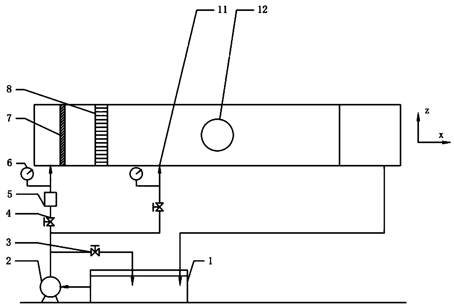
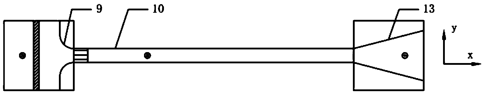
[0016] 1-2, the present invention consists of three parts: mainstream circulation pipeline, jet fluid circulation pipeline and PIV system. The mainstream circulation pipeline includes a water tank 1, a centrifugal pump 2, an overflow valve 3, a speed control valve 4, an electromagnetic flowmeter 5, a pressure gauge 6, a filter screen 7, a grid rectification section 8, two-dimensional channel inlet 9, two Dimensional channel 10, the outlet 13 of the two-dimensional channel and necessary loop connectors. The width of the two-dimensional channel is more than 10 times the height, which ensures that the flow at the center plane of the span width is a two-dimensional flow. The channel is made of 20mm thick transparent plexiglass to facilitate visual observation of the flow.

[0017] The jet pipeline includes a water tank 1, a centrifugal pump 2, an overflow valve 3, a...


PUM


Abstract

The invention aims at providing a device for testing the jet flow drag reduction effect of a two-dimensional plane. The device comprises a water tank, a water pump and a test section, wherein the test section comprises a two-dimensional channel, a two-dimensional channel inlet is arranged at one end of the two-dimensional channel, a two-dimensional channel outlet is arranged at the other end of the two-dimensional channel, the two-dimensional channel inlet is in a gradually reducing shape, the two-dimensional channel outlet is in a gradually expanding shape, a grid type rectifying section is arranged between the two-dimensional channel inlet and the two-dimensional channel, the water pump is communicated with the water tank, the water pump is communicated with the two-dimensional channel inlet through an inlet pipeline, the two-dimensional channel outlet is communicated with the water tank through an outlet pipeline, a speed regulator valve, an electromagnetic flow meter and a pressure meter are arranged on the inlet pipeline, the inlet pipeline is also communicated with a backflow pipeline on which an overflow valve is arranged, and the backflow pipeline is communicated with the water tank. The device has the advantages of low cost, compact structure, small size, convenience in daily maintenance and low noise. The device can be used for testing the drag reduction effect of jet flow surfaces and non-smooth surfaces and can also be used for conventional fluid dynamic tests.

Description

technical field [0001] The invention relates to a test device, in particular to a drag reduction effect test device. Background technique [0002] At present, relevant scholars at home and abroad have carried out extensive and in-depth theoretical exploration and applied research on the problem of motion drag reduction between fluid and solid interfaces, and have successfully achieved remarkable progress in many aspects. Since the problem of drag reduction can directly affect the energy consumption and mechanical properties of equipment, the research on this problem has always been concerned by experts and scholars from various countries. The research methods are mainly from theoretical analysis, numerical simulation, model test and other aspects. The drag reduction performance of the sample is tested in the test device and the required conclusions are drawn, and then put into practical engineering applications. Whether it is theoretical analysis or numerical calculation, t...

Claims


Application Information

Patent Timeline
Patent Type & Authority Applications(China)
IPC IPC(8): G01M10/00
Inventor 赵刚李芳刘维新孙壮志
Owner HARBIN ENG UNIV
Why Eureka
Try Eureka