Soot-blowing control device and method for boiler furnace based on heat flow online measurement

A boiler furnace and control device technology, applied in control systems, lighting and heating equipment, steam generation, etc., can solve the problems of increased contamination model errors, poor stability and adaptability, and unsatisfactory application effects, saving maintenance. Workload, improve accuracy, reduce boiler failure effect

A boiler furnace and control device technology, applied in control systems, lighting and heating equipment, steam generation, etc., can solve the problems of increased contamination model errors, poor stability and adaptability, and unsatisfactory application effects, saving maintenance. Workload, improve accuracy, reduce boiler failure effect

CN101975400AInactive Publication Date: 2011-02-16SOUTHEAST UNIV

Image

  • Soot-blowing control device and method for boiler furnace based on heat flow online measurement
  • Soot-blowing control device and method for boiler furnace based on heat flow online measurement
  • Soot-blowing control device and method for boiler furnace based on heat flow online measurement

Examples


Embodiment Construction

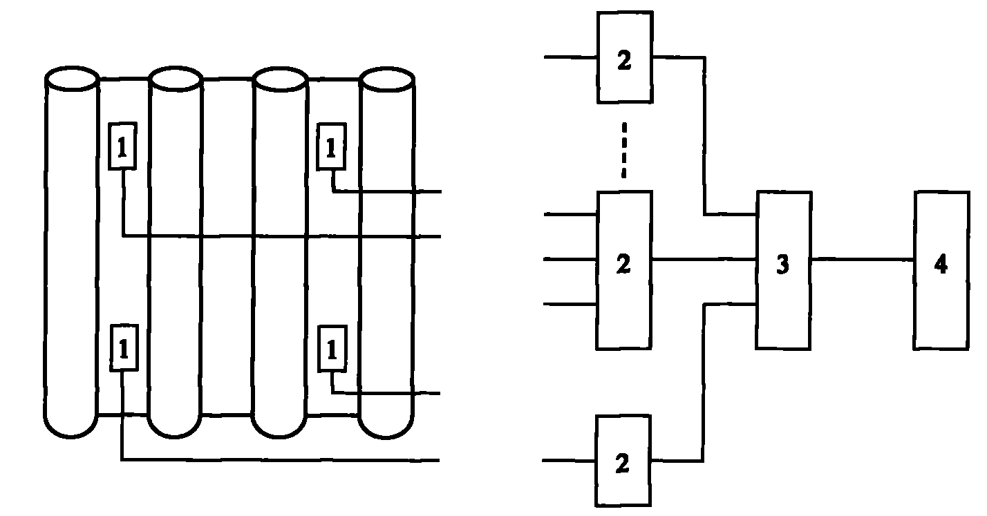
[0027] like figure 1 As shown, the boiler furnace soot blowing control device based on heat flow online measurement according to the present invention includes four parts: heat flow sensor 1 , multiplexer 2 , data collector 3 and industrial computer 4 .

[0028] Select 1 to 4 representative points within the purging radius of each sootblower distributed in the boiler furnace to arrange a heat flow sensor 1 respectively. The monitoring range of the heat flow sensor is preferably a circular surface with a radius of less than 2m. The flow sensors 1 are combined to construct a sensor network for monitoring the contamination of the heating surface of the boiler furnace.

[0029] In this embodiment, the heat flow sensor 1 is a thin-foil heat flow sensor with a circulating water cooling and heat receiving sleeve, which can withstand heat up to 1500°C and can work stably for a long time in the high temperature environment of the boiler furnace. The sensing body of the thermal flow se...


PUM


Abstract

The invention discloses a soot-blowing control device for a boiler furnace based on heat flow online measurement, which comprises a heat flow sensor, a multiplexer, a data collector and an industrial personal computer, wherein the heat flow sensor is arranged on a film-type water wall fin at the periphery of the boiler furnace and connected to the input end of the multiplexer and used for transmitting collected heat flow to the multiplexer; the multiplexer is sequentially connected with the data collector and the industrial personal computer and used for multi-channel switching, signal amplifying and filtering; the data collector is used for converting a heat flow analog signal to a digital signal; and the industrial personal computer is used for analyzing the digital signal transmitted from the multiplexer and sending a soot-blowing signal. The invention can be used for various coal-fired power plants; and according to fouling conditions of heating surfaces in each region of the boiler furnace, realizes the sweeping in a demand quantity for the required region, improves the accuracy and the real time of fouling diagnosis for the heating surfaces of the boiler furnace, reduces the boiler failure, prolongs the lifetime of a soot-blower, saves the maintenance workload of the soot-blower, and the like.

Description


Claims


Application Information

Patent Timeline
16 Feb 2011
Publication
CN101975400A