Eureka AIR delivers breakthrough ideas for toughest innovation challenges, trusted by R&D personnel around the world.

Heat exchange device

A technology of heat exchange device and micro-channel heat exchanger, which is applied in the directions of household heating, heating mode, household heating, etc., can solve the problems of unreasonable combination structure setting, long flow distance of condensate water, and obstruction of air circulation, etc. Improve drainage performance, reasonable design of air duct flow path, and good heat exchange effect

Inactive Publication Date: 2011-02-16
GD MIDEA AIR-CONDITIONING EQUIP CO LTD
View PDF6 Cites 4 Cited by
  • Summary
  • Abstract
  • Description
  • Claims
  • Application Information

AI Technical Summary

Problems solved by technology

[0002] At present, when the micro-channel heat exchanger is used as the heat exchanger of the indoor unit of the cabinet air conditioner, condensed water will be generated on the surface. Installed between the headers, the headers are located on the upper and lower sides, and the straight section between the fins set between adjacent flat tubes and the air heat exchange is often horizontal, and water will appear on the edge; When the fins have slots, the condensed water will flow from the upper fins to the lower fins along the slots. Although the drainage is realized, due to the gap between the air inlet side fins and the air outlet side fins The combined structure is unreasonable. The condensed water of the upper fins needs to pass through all the lower fins to be finally discharged. The condensed water has a long flow distance, which affects the heat exchange effect during the flow process. The wind resistance is large, which hinders Air circulation reduces heat transfer efficiency

Method used


Image

  • Heat exchange device
  • Heat exchange device
  • Heat exchange device

Examples


Embodiment Construction

[0035] The present invention will be described in further detail below through specific embodiments and in conjunction with the accompanying drawings.

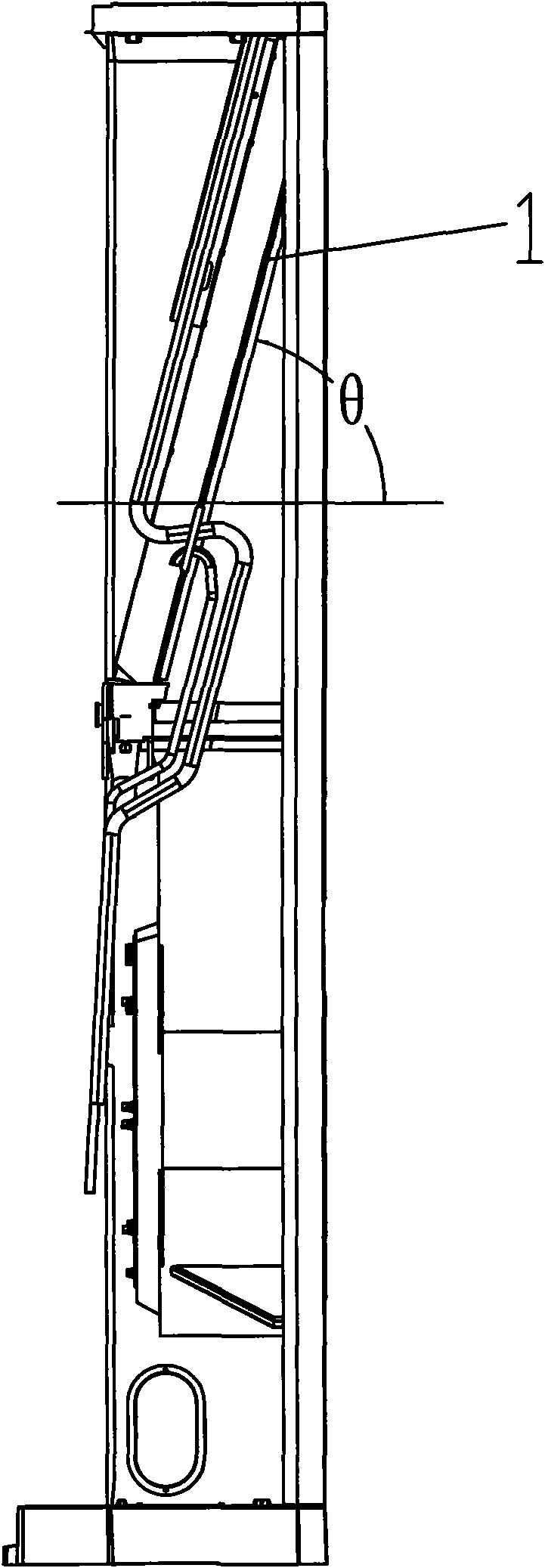
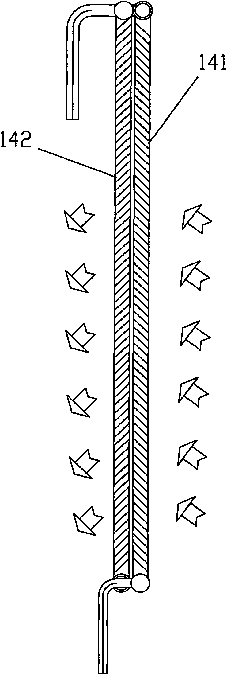
[0036] Such as figure 1 As shown, a heat exchange device is applied to a heat exchanger of an indoor unit or an outdoor unit of a cabinet air conditioner, such as an evaporator. It includes at least one microchannel heat exchanger 1 . See figure 1 , the microchannel heat exchanger arranged inside the indoor unit of the cabinet air conditioner forms an included angle θ with the horizontal direction, 30°≤θ≤90°. combine Figure 8 It can be seen that the microchannel heat exchanger 1 generally includes a first header 11, a second header 12 arranged in parallel with a certain distance from the first header 11, and a second header connected between the first header 11 and the second header. Among the flow tubes 12 are several flat tubes 13 spaced at a certain distance from each other and several fins 14 respectively arranged bet...


PUM

PropertyMeasurementUnit
Spacingaaaaaaaaaa

Abstract

The invention discloses a heat exchange device, which comprises at least one micro-channel heat exchanger, wherein the micro-channel heat exchanger comprises a first collecting pipe, a second collecting pipe arranged in parallel with the first collecting pipe in certain distance, a plurality of oblate pipes arranged between the first collecting pipe and the second collecting pipe and mutually spaced in certain distance, and a plurality of fins arranged between the oblate pipes respectively; a plurality of micro-channels for communicating the first collecting pipe and the second collecting pipe are formed in the oblate pipes; and the heat exchange device comprises an air inlet fin and an air outlet fin, wherein the air inlet fin and the air outlet fin are positioned on two micro-channel heat exchangers arranged side by side in certain clearance, or the air inlet fin and the air outlet fin are positioned on the same micro-channel heat exchanger, the surface of the air inlet fin is inclined at any position towards the air outlet side, and the surface of the air outlet fin is downwards inclined towards the air outlet side. The air flue flow path has reasonable design, is favorable for improving the heat exchange capability of the heat exchanger and reducing the air flue resistance, and has extremely good heat exchange effect.

Description

Technical field: [0001] The invention relates to a heat exchange device, which belongs to the technical field of air conditioning. Background technique: [0002] At present, when the micro-channel heat exchanger is used as the heat exchanger of the indoor unit of the cabinet air conditioner, condensed water will be generated on the surface. Installed between the headers, the headers are located on the upper and lower sides, and the straight section between the fins set between adjacent flat tubes and the air heat exchange is often horizontal, and water will appear on the edge; When the fins have slots, the condensed water will flow from the upper fins to the lower fins along the slots. Although the drainage is realized, due to the gap between the air inlet side fins and the air outlet side fins The combined structure is unreasonable. The condensed water of the upper fins needs to pass through all the lower fins to be finally discharged. The condensed water has a long flow d...

Claims


Application Information

Patent Timeline
IPC IPC(8): F24F13/22F25B39/02F25B39/00F24F13/30F28F1/12
Inventor 徐绍勇佐藤宪一郎林飞任志洁
Owner GD MIDEA AIR-CONDITIONING EQUIP CO LTD
Why Eureka
Eureka Blog
Learn More