Method for correcting image sensor

An image sensor, pixel technology, applied in instruments, data processing input/output process, electrical digital data processing and other directions, can solve problems such as signal strength effects

Inactive Publication Date: 2011-02-16
QISDA SUZHOU +1
View PDF3 Cites 5 Cited by
  • Summary
  • Abstract
  • Description
  • Claims
  • Application Information

AI Technical Summary

Problems solved by technology

However, the signal strength of the optical touch panel detected by the image detector is easily affected by the light source, temperature, or other external factors that are difficult to control. Therefore, the image detector performs the above detection A set of parameter values ​​applied during operation also needs to be corrected appropriately to ensure that the touch device can continue to work correctly

Method used


Image

  • Method for correcting image sensor
  • Method for correcting image sensor
  • Method for correcting image sensor

Examples


Embodiment Construction

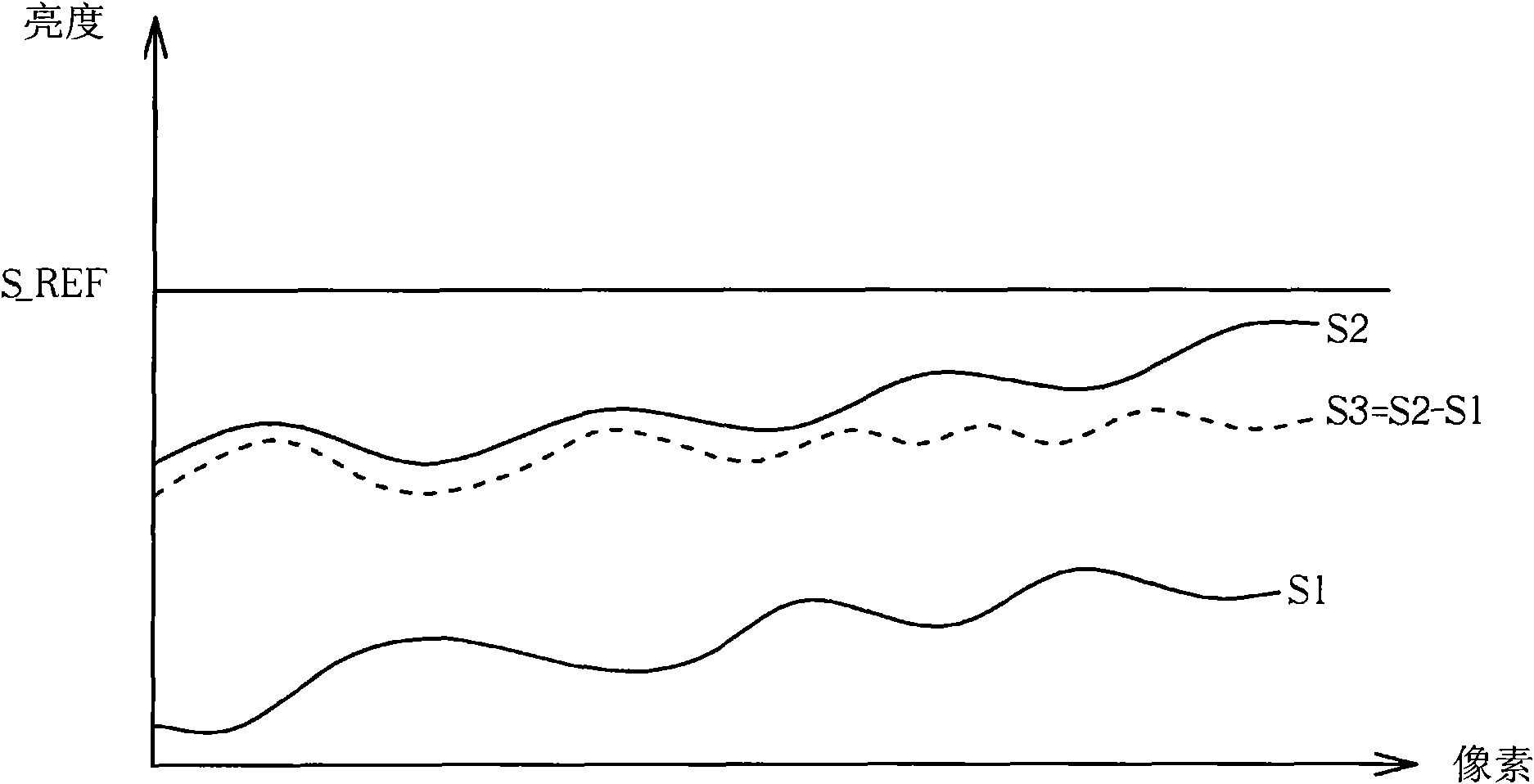
[0024] The invention discloses a method for calibrating an image sensor. In this method, when the image sensor is turned on, it is first calibrated according to specific conditions, and after the image sensor is turned on, at regular intervals, a part of the frame originally scheduled for image processing is intercepted. The brightness magnification ratio of the group is calibrated so as to make the image sensor operate correctly in response to any environmental changes that may occur during the operation of the image sensor without affecting the general operation of the image sensor.

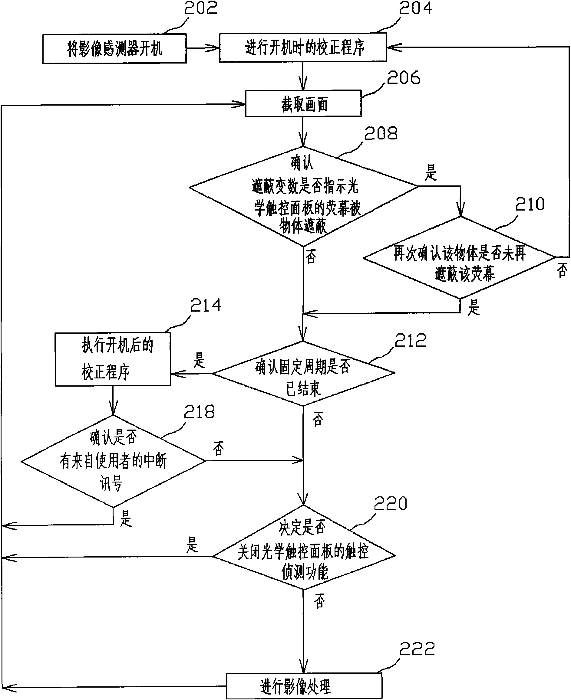
[0025] see figure 2 , which is a flowchart of a method for calibrating an image sensor disclosed in the present invention. Such as figure 2 As shown, the method for calibrating an image sensor disclosed in the present invention includes the following steps:

[0026] Step 202: Turn on the image sensor;

[0027] Step 204: Carry out the calibration procedure when starting up;

[0028] Step 20...


PUM


Abstract

The invention discloses a method for correcting an image sensor, which comprises the following steps: correcting a brightness amplification factor used by the image sensor when the image sensor is started; and truncating at least one picture frame (but not all) from a plurality of picture frames predetermined for image processing in unit time whenever a fixed cycle is finished after the start of the image sensor, and correcting the brightness amplification factor according to the truncated picture frame. The method precludes the possibility that the screen of an optical touch panel is obscured by an object in advance to keep parameter values used by the image sensor accurate by running correction programs in the starting process, and continuously keeps the accuracy of the brightness amplification factor on the premise of not affecting the display quality of the screen.

Description

technical field [0001] The invention discloses a method for calibrating an image sensor, especially a method for calibrating when the image sensor is powered on or continuously calibrating parameters to ensure the normal operation of the image sensor. Background technique [0002] Generally, in a touch device equipped with an optical touch panel, an image sensor will be provided on the optical touch panel to detect any effective touch behavior of the user on the optical touch panel, and make the touch device It can respond to the touch command sent by the user to the optical touch panel. [0003] When the image sensor is in operation, it first intercepts light from the optical touch panel as an analog signal, and then passes through the analog front end (Analog Front End, AFE) and analog-to-digital converter included on the motherboard of the touch device. The analog signal is converted into a digital signal to obtain the brightness of each pixel position on the current opt...

Claims


Application Information

Patent Timeline
Patent Type & Authority Applications(China)
IPC IPC(8): G06F3/042
Inventor 李俊仁何建贤张皓崴赖育稚张正宽毛昭凯
Owner QISDA SUZHOU
Why Eureka
Try Eureka