
Single-phase multi-pole switched reluctance motor

A multi-pole switching, reluctance motor technology, applied in electric components, electrical components, electromechanical devices and other directions, can solve the problems of single-phase switched reluctance motor can not operate normally, can not effectively eliminate residual magnetism, etc., to eliminate residual magnetism , the effect of improving efficiency and reducing costs

Inactive Publication Date: 2013-07-24
ANHUI QUANCHAI GROUP
View PDF0 Cites 2 Cited by
  • Summary
  • Abstract
  • Description
  • Claims
  • Application Information

AI Technical Summary

Problems solved by technology

At present, multi-phase switched reluctance motors use coils and freewheeling diodes to eliminate residual magnetism. However, freewheeling diodes can only protect the coils and cannot effectively eliminate residual magnetism.
The residual magnetism has a greater impact on the single-phase switched reluctance motor. If the residual magnetism is not eliminated, the single-phase switched reluctance motor will not operate normally

Method used


Image

  • Single-phase multi-pole switched reluctance motor
  • Single-phase multi-pole switched reluctance motor
  • Single-phase multi-pole switched reluctance motor

Examples


Embodiment Construction

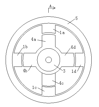
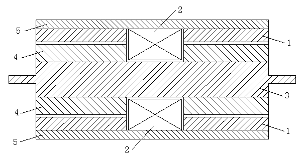
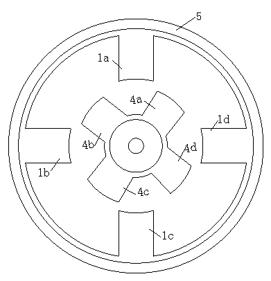
[0011] A single-phase multi-pole switched reluctance motor includes a rotor and a stator, the stator includes a stator magnetic pole 1 and an excitation coil 2, the rotor includes a rotor core 3 and a rotor magnetic pole 4, and the rotor magnetic poles are 4 sets Set on the rotor core 3, the stator magnetic pole 1 is located outside the rotor magnetic pole 4, the stator magnetic pole 1 and the excitation coil 2 are fixed in the motor housing 5, the signal input terminal of the motor controller 6 is connected to the position sensor, and the motor controls The signal output terminal of the device 6 is connected to the excitation coil 2 through the oscillator 7, such as figure 1 Shown. The excitation coil 2 is located between the motor housing 5 and the rotor core 3. The motor controller 6 is connected to the oscillator 7 through an electronic switch 8, the oscillator 7 is connected to the excitation coil 2, and the oscillator 7 is an LC series attenuated oscillator. In the LC se...


PUM


Abstract

The invention relates to a single-phase multi-pole switched reluctance motor which comprises a rotor and a stator, wherein the stator comprises a stator magnetic pole and an excitation coil; the rotor comprises a rotor iron core and a rotor magnetic pole; the rotor magnetic pole is sleeved on the rotor iron core; the stator magnetic pole is positioned outside the rotor magnetic pole; the stator magnetic pole and the excitation coil are fixedly arranged in a motor shell; and a signal input end of a motor controller is connected with a position sensor and a signal output end is connected with the excitation coil through an oscillator. The single-phase multi-pole switched reluctance motor is only provided with one excitation coil and one control circuit, once the coil is electrified, the stator magnetic pole and the rotor magnetic pole generate electromagnetic torques, thus the low is lowered, and the efficiency is improved. In addition, the oscillator is arranged in the single-phase multi-pole switched reluctance motor, the magnetic pole direction of the magnetic iron core is changed with the change of current; and with the continuous attenuation of an oscillation current, the magnetization intensity is gradually weakened until to be close to zero; and thus, the residual magnetism can be effectively eliminated.

Description

Technical field [0001] The invention relates to a motor, in particular to a single-phase multi-pole switched reluctance motor. Background technique [0002] Switched reluctance motors are divided into multi-phase switched reluctance motors and single-phase switched reluctance motors. The multi-phase switched reluctance motor has the advantages of high efficiency and large starting torque. However, because the multi-phase switched reluctance motor can only turn on one phase at a time, and then turn on each phase in turn, there is only one phase of electromagnetic output per unit time. Torque, the rest of the phases are in an idle state, resulting in great waste from the motor structure to the control circuit. [0003] In addition, for switched reluctance motors, how to eliminate residual magnetism in the magnetic poles is very important. At present, the multi-phase switched reluctance motor uses a coil and a freewheeling diode to eliminate the residual magnetization. However, the ...

Claims


Application Information

Patent Timeline
Patent Type & Authority Patents(China)
IPC IPC(8): H02K29/06H02K29/00H02K1/24H02K11/00H02K11/21
Inventor 石云艾
Owner ANHUI QUANCHAI GROUP
Learn More