
Prestack reverse time migration imaging method and device

Inactive Publication Date: 2011-02-23
INST OF GEOLOGY & GEOPHYSICS CHINESE ACAD OF SCI +1
View PDF7 Cites 16 Cited by
  • Summary
  • Abstract
  • Description
  • Claims
  • Application Information

AI Technical Summary

Problems solved by technology

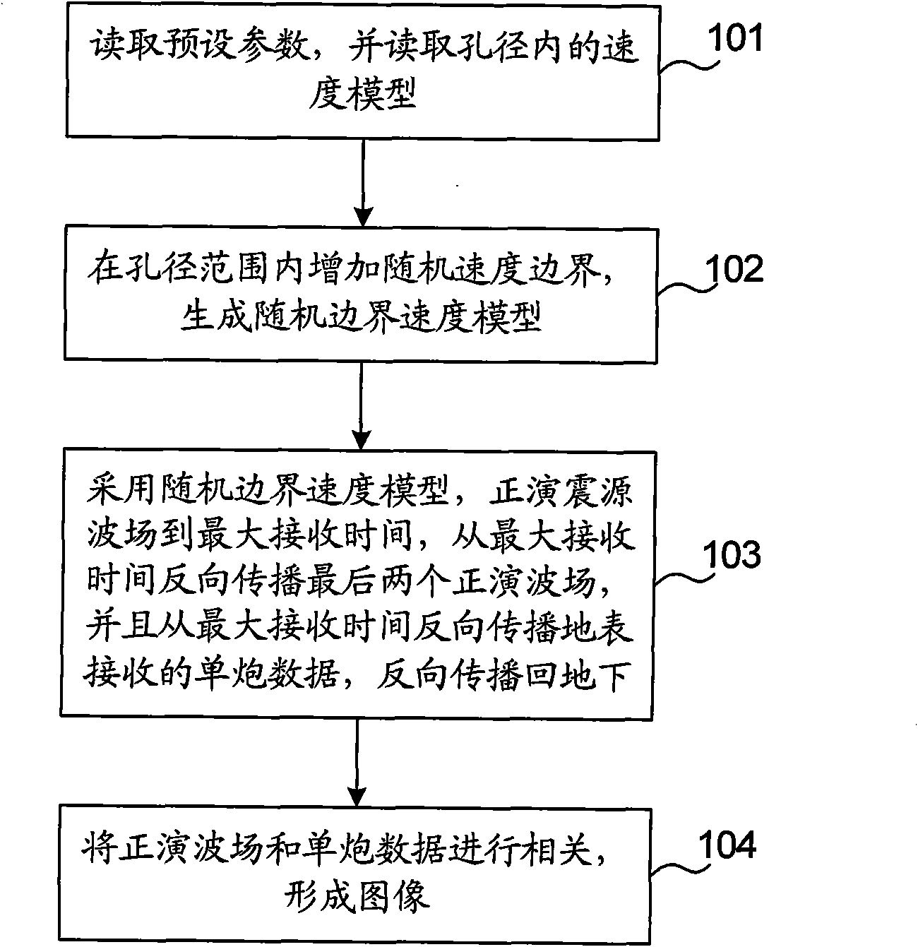
[0008] The present invention provides a method and device for pre-stack reverse time migration imaging, which are used to solve the problems of large data storage space and slow imaging speed in the prior art, and reduce the storage space required for reverse time migration imaging. Need to improve the speed of reverse time migration imaging

Method used


Image

  • Prestack reverse time migration imaging method and device
  • Prestack reverse time migration imaging method and device
  • Prestack reverse time migration imaging method and device

Examples


Embodiment 2

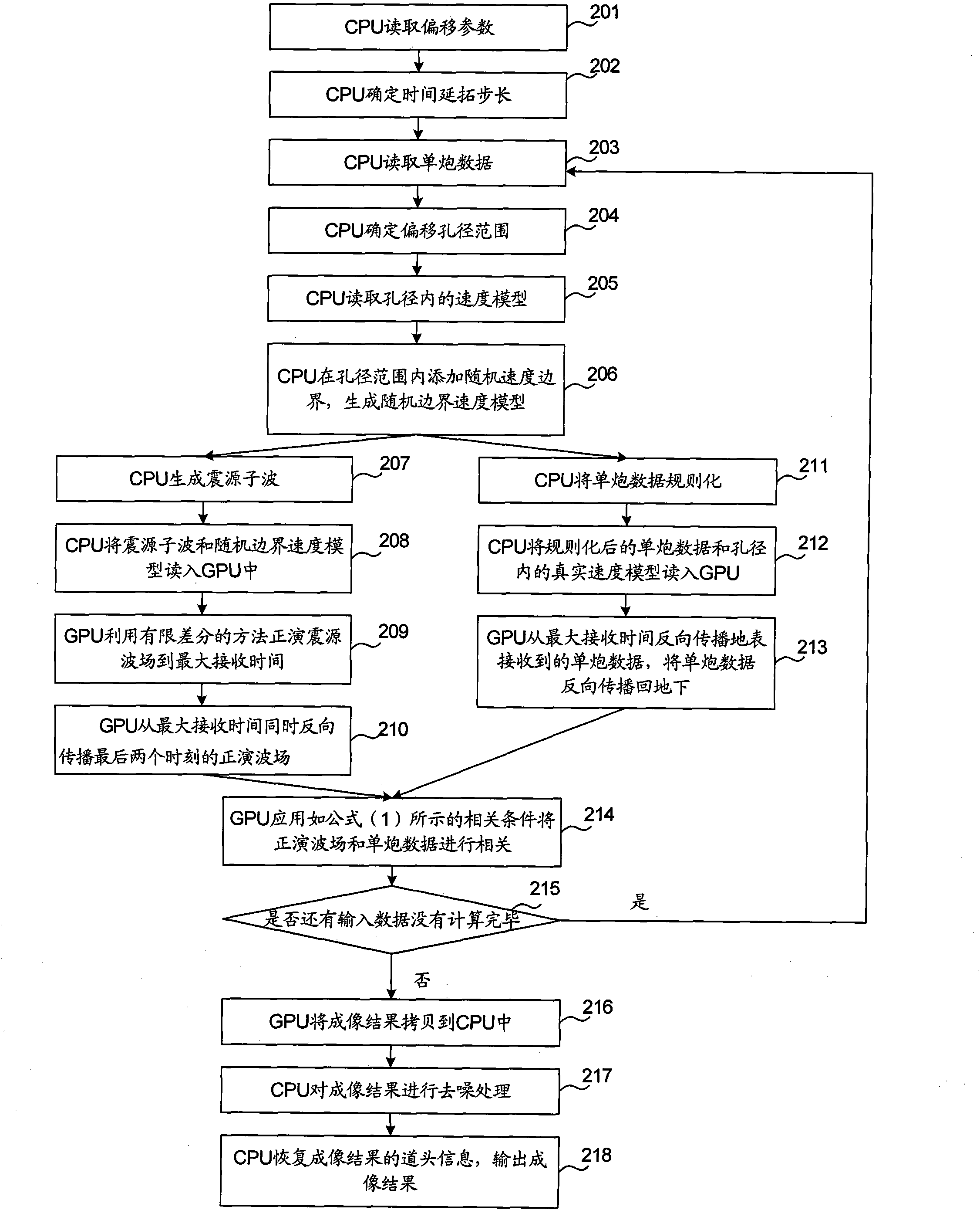
[0065] In Embodiment 2, the sequence of each step can be specifically referred to in the attached figure 2 . Steps 207-210 and steps 211-213 can be performed at the same time, that is to say, a series of processing steps involving forward wavefield backpropagation and a series of processing steps involving single shot data backpropagation can be performed simultaneously . In step 214, once the GPU receives the forward wave field and single-shot data, it can correlate the data without waiting for all the data to be propagated.

[0066] In the second embodiment, the combination of CPU and GPU is used for imaging, and the GPU is responsible for processing the continuation part of the seismic wave field with a large amount of calculation, thereby improving the imaging speed.

[0067] Such as image 3 Shown is a schematic structural diagram of the prestack reverse time migration imaging device of the present invention, which includes: a preprocessing module 11 , a generating mo...


PUM


Abstract

The invention provides a prestack reverse time migration imaging method and a prestack reverse time migration imaging device. The method comprises the following steps of: increasing random speed boundaries in an aperture range to generate a random boundary speed model; forwarding a focus wave field to the maximal receiving time by using the random boundary speed model, reversely propagating the last two forwarding wave fields from the maximal receiving time, reversely propagating single shot data received by the earth surface from the maximal receiving time and reversely propagating the single shot data back to an underground place; and correlating the forwarding wave fields and the single shot data to form an image. By the method provided by the invention, the prestack reverse time migration imaging speed can be increased and the requirements on a storage space is reduced.

Description

technical field [0001] Embodiments of the present invention relate to the field of imaging technology, and in particular, to a method and device for prestack reverse time migration imaging. Background technique [0002] With the continuous deepening of oil and gas field exploration, oil and gas exploration has attracted more and more attention. The traditional migration method cannot delineate the boundary of the salt dome to image the sub-salt structure, but the reverse time migration (RTM) imaging method uses a double wave equation, which can accurately describe the wave propagation process. Accurate imaging of steep dip angles and inversion structures, using limited migration methods to image complex geological structures. [0003] The existing prestack reverse time migration imaging method includes the following steps: [0004] Read the velocity model in the aperture, generate the source wavelet, use the finite difference method to forward model the source wave field t...

Claims


Application Information

Patent Timeline
IPC IPC(8): G01V1/28
Inventor 李博
Owner INST OF GEOLOGY & GEOPHYSICS CHINESE ACAD OF SCI
Learn More