Regular octagonal template-based board camera intrinsic parameter calibration method

A camera internal parameter and camera calibration technology, applied in the field of computer vision, can solve the problems of sensitive initial value selection, unsuitable for placing accurate calibration reference objects, poor stability, etc.

Inactive Publication Date: 2011-02-23
BEIJING UNIV OF TECH
View PDF0 Cites 15 Cited by
  • Summary
  • Abstract
  • Description
  • Claims
  • Application Information

AI Technical Summary

Problems solved by technology

These traditional algorithms are cumbersome, slow in operation speed, sensitive to initial value selection, poor in stability and other inherent defects.
The occasion where the vehicle camera ranging system is located is sometimes not suitable for placing an accurate calibration reference object

Method used


Image

  • Regular octagonal template-based board camera intrinsic parameter calibration method
  • Regular octagonal template-based board camera intrinsic parameter calibration method
  • Regular octagonal template-based board camera intrinsic parameter calibration method

Examples


Embodiment Construction

[0050] The present invention will be further described below in conjunction with the accompanying drawings and examples.

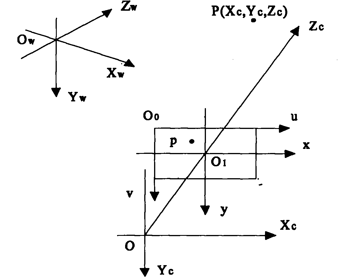
[0051] figure 1 It is a schematic diagram of the computer image coordinate system (u, v), the imaging plane coordinate system (x, y), the camera coordinate system (Xc, Yc, Zc) and the world coordinate system (Xw, Yw, Zw). Computer image coordinate system (u, v): Each digital image is stored in the form of an array in the computer, and the value of each element (pixel) of the array is the brightness of the image point. The origin is located at the upper left corner of the image plane, and the coordinates (u, v) of each pixel represent the number of columns and rows of the pixel in the array, respectively. Imaging plane coordinate system: the origin is located at the intersection of the camera optical axis and the image plane, and the x and y axes are parallel to the u and v axes respectively, expressed in physical units (such as millimeters). Camera coord...


PUM


Abstract

The invention discloses a camera intrinsic parameter calibration method, and relates to the field of computer vision, in particular occasions for calibrating cameras by ranging through a board camera. The technical scheme is that: a regular octagonal template is adopted as a calibration template; the template is shot by the camera in at least three directions, and at least three images of the template can be acquired; coordinate values of nine characteristic points in a single template image are acquired by a corner detection method which can be accurate to a sub-pixel level, and coordinates of four end points in directions of four diagonals are solved so as to solve coordinates of two ring points; coordinates of at least six ring points are obtained according to the at least three images of the template in different directions so as to obtain a camera intrinsic parameter matrix, and the camera intrinsic parameter is obtained. The camera intrinsic parameter calibration method self-calibrates the camera intrinsic parameter by adopting a single regular octagonal template and is a practical calibration method.

Description

Technical field: [0001] The invention relates to the field of computer vision, in particular to the occasion of calibrating the camera by using the distance measurement of the vehicle-mounted camera. Background technique: [0002] Applying computer vision and image processing technology to vehicle driving assistance system can effectively provide safety guarantee for vehicle driving. In computer vision, using visual information to perceive the environment and determining the position of the target in the 3D world from the 2D projected image, camera calibration is an essential step. The so-called camera calibration is the process of obtaining the parameters of the camera imaging geometric model through experiments. The internal parameters of the camera are parameters that reflect the internal geometric and optical characteristics of the camera. [0003] The traditional camera calibration method based on the three-dimensional calibration object adopts the technology in photo...

Claims


Application Information

Patent Timeline
Patent Type & Authority Applications(China)
IPC IPC(8): G06T7/00
Inventor 冯能莲郝静宾洋周大森
Owner BEIJING UNIV OF TECH
Why Eureka
Try Eureka