A touch screen glass conveying and discharging device

A technology of discharging device and touch screen, applied in conveyor objects, transportation and packaging, furnace and other directions, can solve the problems of inconvenient removal of glass, affecting production efficiency, glass falling, etc., to facilitate removal of glass, reduce movement frequency, prevent glass falling effect

Active Publication Date: 2021-12-17
四川省长江华云电子技术有限公司
View PDF14 Cites 0 Cited by
  • Summary
  • Abstract
  • Description
  • Claims
  • Application Information

AI Technical Summary

Problems solved by technology

[0002] During the production process of touch screen glass, different process sections need to be transferred and conveyed. At present, when transferring and conveying touch screen glass, manual or pneumatic suction cups are usually used to discharge the glass, and the efficiency of manual discharge is low. Affects production efficiency; the way of pneumatic suction cups can only stack the glass in direct contact. Since the contact surface between the glasses is relatively smooth, there is a moving adsorption force between them, which is not convenient for the subsequent process to take out the glass; and the existence of pneumatic suction cups Risk of falling glass

Method used


Image

  • A touch screen glass conveying and discharging device
  • A touch screen glass conveying and discharging device
  • A touch screen glass conveying and discharging device

Examples


Embodiment 1

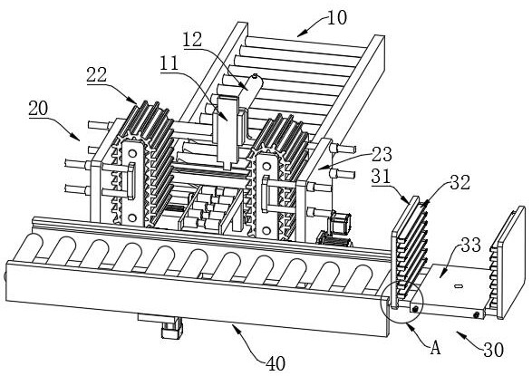
[0039] Such as Figure 1 to Figure 7 As shown, a touch screen glass conveying and discharging device includes: a conveying line 10 , a stacking mechanism 20 and a discharging frame 30 .

[0040] Specifically, the conveying line 10 is used for conveying glass, and a push plate 11 is arranged above the outlet end thereof, and the push plate 11 is moved vertically so as to change the height position of the push plate 11 . The push plate 11 is arranged to move along the conveying direction of the conveying line 10 , and is used to simultaneously push the glass stacked in the stacking mechanism 20 into the discharge frame 30 .

[0041] Specifically, the stacking mechanism 20 is arranged at the outlet end of the conveying line 10 . The stacking mechanism 20 includes a conveying roller set 21 parallel to the conveying line 10, and all rollers of the conveying roller set 21 can actively rotate for moving glass.

[0042]Conveyor belts 22 parallel to each other are arranged on both si...

Embodiment 2

[0048] Such as figure 1 , Figure 4 As shown, a touch screen glass conveying and discharging device further includes a material frame track 40 , which is arranged at the outlet end of the stacking mechanism 20 and is used for conveying the material frame 30 . The conveying direction of the material frame track 40 and the conveying direction of the conveying line 10 are perpendicular to each other.

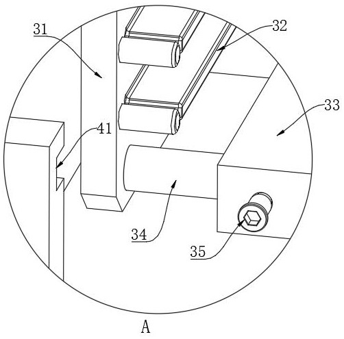
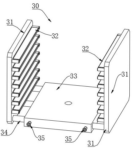
[0049] More specifically, such as figure 2 , image 3 As shown, the discharge frame 30 also includes a bottom plate 33, and the side plates 31 are pierced through the bottom plate 33 by at least two round rods 34 for adjusting the distance between the side plates 31; Locking screw rods 35 are pierced on both sides for compressing the round rod 34 . The inner wall of the skeleton on both sides of the material frame track 40 is provided with a bar-shaped groove 41 along the conveying direction. The stability when the discharge frame 30 moves.

[0050] preferred, such as Figu...


PUM


Abstract

The present application provides a touch screen glass conveying and discharging device, including: a conveying line, a stacking mechanism and a discharging frame. The conveying line is used for conveying glass, and a push plate is arranged above the outlet end. The stacking mechanism is set at the exit end of the conveying line; the stacking mechanism includes a set of conveying rollers; conveyor belts are arranged on both sides of the conveying rollers; the conveyor belts are rotated, and the rotation direction of the two sets of conveyor belts is opposite; The convex strips of the group conveyor belts are used in pairs to carry glass; the distance between the two groups of conveyor belts is adjustable. The discharge frame is placed at the outlet end of the stacking mechanism. The discharge frame includes a pair of side plates, and the side plates are provided with flat plates. And the distance between the adjacent flat plates is the same as the distance between the adjacent convex strips; the distance between the side plates is adjustable. It has high discharge efficiency and safety, and it is convenient to take out the glass in the subsequent process.

Description

technical field [0001] The invention belongs to the technical field of transportation or storage devices, and in particular relates to a touch screen glass conveying and discharging device. Background technique [0002] During the production process of touch screen glass, different process sections need to be transferred and conveyed. At present, when transferring and conveying touch screen glass, manual or pneumatic suction cups are usually used to discharge the glass, and the efficiency of manual discharge is low. Affects production efficiency; the way of pneumatic suction cups can only stack the glass in direct contact. Since the contact surface between the glasses is relatively smooth, there is a moving adsorption force between them, which is not convenient for the subsequent process to take out the glass; and the existence of pneumatic suction cups Risk of glass falling. Contents of the invention [0003] In order to solve the deficiencies of the prior art, the prese...

Claims


Application Information

Patent Timeline
Patent Type & Authority Patents(China)
IPC IPC(8): B65G49/06
CPCB65G49/064B65G49/068
Inventor 李洪林张策胡城生任伟
Owner 四川省长江华云电子技术有限公司
Why Eureka
Try Eureka