Fast side discharge method of walking hearth furnace

A side-discharging, rapid technology, applied to furnaces, furnace components, lighting and heating equipment, etc., can solve the problems that the furnace cannot meet the process requirements, affect the thermal processing performance of the billet, and cool down, so as to improve labor productivity and improve heating Quality, the effect of reducing the frequency of exercise

Active Publication Date: 2016-05-04
韩根望
View PDF5 Cites 0 Cited by
  • Summary
  • Abstract
  • Description
  • Claims
  • Application Information

AI Technical Summary

Problems solved by technology

Whether the current side discharge method of the stepping bottom furnace adopts cantilever roller discharge or side discharge machine discharge, each time the moving bed moves a step cycle, the furnace can discharge one material, because one step cycle is generally Including multiple actions such as rising-forward-falling-backward, a stepping cycle takes a long time, limited by the stepping cycle, in some occasions that require fast discharge, although multiple billets have been heated, However, the furnace cannot meet the technological requirements of producing multiple materials one by one
If two or more pieces of material are released from the furnace at the same time, due to problems such as the rhythm of the thermal processing process, the temperature of the billet that cannot be thermally processed immediately after being released from the furnace will be cooled due to waiting for processing outside the furnace, which will affect the thermal processing performance of the billet

Method used


Image

  • Fast side discharge method of walking hearth furnace
  • Fast side discharge method of walking hearth furnace
  • Fast side discharge method of walking hearth furnace

Examples


Embodiment Construction

[0023] The present invention will be further described in detail below in conjunction with the accompanying drawings and specific embodiments.

[0024] In summary, the present invention discloses a method for quick side discharge of a walking hearth furnace, comprising the following steps:

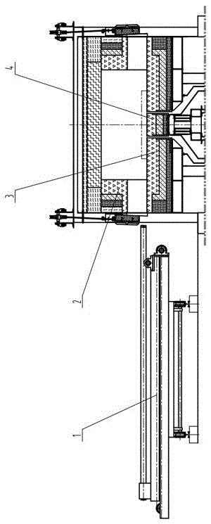
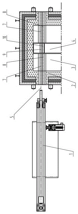
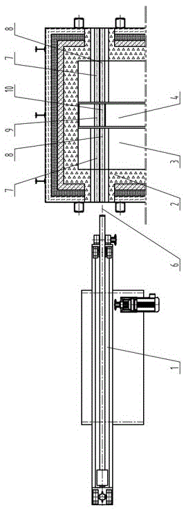
[0025] Step 1: The moving bed 4 rises from the initial position, that is, the rear low position. When the upper surface of the moving bed 4 is at the same height as the upper surface of the fixed bed 3, the moving bed 4 lifts the billet placed on the fixed bed and continues to rise to the highest position ;

[0026] Step 2: After the moving bed 4 reaches the highest point, it stops moving upwards, and under the push of the driving device, it advances horizontally toward the discharge end for a distance of more than one material distance. After the moving bed 4 reaches the position, the moving bed 4 stops moving;

[0027] Step 3: The movable bed 4 moves vertically downwards, and stops when...


PUM


Abstract

The invention discloses a fast side discharge method of a step-by-step bottom-type furnace. The fast side discharge method is characterized in that the step of pause during discharge when the height of a movable bed is level to that of a fixed bed is added so that blanks are pushed out of the furnace under the joint supporting of the movable bed and the fixed bed, meanwhile in a step-by-step cycle period of the movable bed, one, two or more than two blanks can be pushed out of the furnace in sequence through transverse moving of a discharging machine located on the outer side of the furnace, the discharge frequency of the step-by-step bottom-type furnace can be one time or more than twice of the step-by-step cycle frequency of the movable bed, and therefore the production rhythm of discharging a plurality of blanks in sequence within one minute can be met, the labor productivity of the step-by-step bottom-type furnace is effectively improved, the moving times of the movable bed are reduced, the service life of the movable bed is prolonged, and electricity consumption is reduced. Meanwhile, the transverse moving discharging machine is used for discharging so that the stay time of a push rod of a pusher in the furnace is very short, heat taken away by the water-cooling push rod is very little, influence on a temperature field of a discharge zone is small, the heating quality of the blanks is remarkably improved, and the heat efficiency of the a heating furnace is improved.

Description

technical field [0001] The invention relates to the technical field of walking hearth furnaces, in particular to a rapid side discharge method for walking hearth furnaces. Background technique [0002] At present, the walking hearth furnaces used in various industries generally have two discharging methods: end discharging and side discharging. On the slope of the fixed bed (also known as the fixed bottom) of the head, the billet slides out of the furnace by its own weight, or the billet is dragged out of the furnace by a drag machine. The end discharge method is currently less used due to the large heat loss of the furnace mouth and the difficulty in arranging burners on the end wall. There are also two ways of side discharge: one is to install cantilever rollers on the end wall of the furnace discharge end, the bearings and transmission mechanisms of the cantilever rollers are arranged outside the furnace, the roller body extends into the furnace, and the billet is placed...

Claims


Application Information

Patent Timeline
Patent Type & Authority Patents(China)
IPC IPC(8): F27D3/00
Inventor 韩根望
Owner 韩根望
Why Eureka
Try Eureka