hydraulic airless pump

An air pump and hydraulic technology, applied in the direction of pumps, piston pumps, liquid variable capacity machines, etc., can solve the problems of shortened service life, high noise and complex structure of seals, and achieve compact structure, increased flow, and low noise. Effect

Inactive Publication Date: 2016-08-17
NINGBO SHENGHENG OPTICS & ELECTRONICS
View PDF5 Cites 0 Cited by
  • Summary
  • Abstract
  • Description
  • Claims
  • Application Information

AI Technical Summary

Problems solved by technology

[0002] Due to the low movement stroke of the existing airless pump, the number of movements of the seal is increased to shorten the service life of the existing airless pump, and the structure is complex, the weight is heavy, and it will generate relatively high noise during use, so it is necessary to improve

Method used


Image

  • hydraulic airless pump
  • hydraulic airless pump

Examples


Embodiment 1

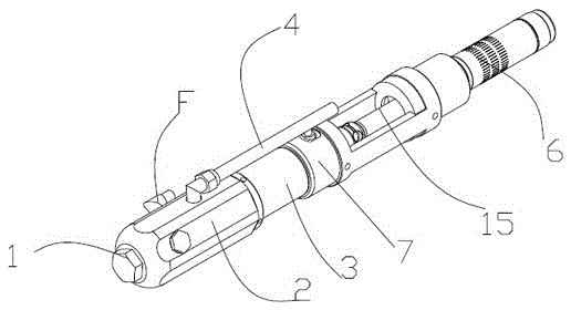
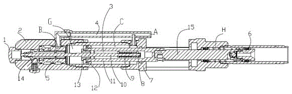
[0011] Such as figure 1 , 2 As shown, the hydraulic airless pump provided by this embodiment includes a pump body 2, a piston assembly 3, a base 7, and a suction assembly 6. The pump body 2 is connected to the piston assembly 3, and the piston assembly 3 and the suction assembly 6 pass through the base The seat 7 is connected. The piston assembly 3 includes a tie rod 10, a second tie rod nut 14, a piston 11, a piston seal 12, and a split cap 13. The piston 11, the piston seal 12 and the split cap 13 form a sealed space. 11 is provided with a tie rod spring 9 and a first tie rod nut 8, the first tie rod nut 8 is connected to the tie rod 10 through the tie rod spring 9, and the other end of the tie rod 10 is connected to the second tie rod nut 14 and is located in the pump body 2.

[0012] When working, the hydraulic fluid flows in from port A of the oil inlet pipe 4 through the hydraulic pump, first flows into the point C, and drives the first tie rod nut 8, tie rod spring 9, tie r...


PUM


Abstract

The invention discloses a hydraulic airless pump for equipment spraying, which comprises a pump body, a piston assembly, a base and a suction assembly, the pump body is connected with the piston assembly, and the piston assembly and the suction assembly are connected through the base. The piston assembly includes a pull rod, a second pull rod nut, a piston, a piston seal and a spliced ​​cap. The piston, piston seal and spliced ​​cap form a sealed space. A pull rod spring and a first pull rod nut are arranged inside the piston. The first pull rod nut passes through the The pull rod spring is connected to the pull rod, and the other end of the pull rod is connected to the second pull rod nut and is located in the pump body. The hydraulic airless pump obtained by the present invention greatly improves its movement stroke during operation, thereby reducing the movement of the seal The number of times prolongs the service life, and the structure is compact, the noise is low, and the flow rate of the product is greatly improved without changing the spraying performance.

Description

Technical field [0001] The invention relates to a hydraulic airless pump for equipment spraying. Background technique [0002] The existing airless pump has a low movement stroke, which increases the number of movements of the sealing element and shortens its service life. It also has a complex structure and heavy weight, and generates high noise during use. Therefore, it is necessary to improve. Summary of the invention [0003] The purpose of the present invention is to provide a hydraulic airless pump with small structure, low noise and increased flow in order to solve the above-mentioned shortcomings of the prior art. [0004] In order to achieve the above objectives, the hydraulic airless pump designed by the present invention includes a pump body, a piston assembly, a base and a suction assembly. The pump body is connected to the piston assembly, and the piston assembly and the suction assembly are connected through the base. The assembly includes a tie rod, a second tie rod ...

Claims


Application Information

Patent Timeline
Patent Type & Authority Patents(China)
IPC IPC(8): F04B9/105
Inventor 沈纪萍
Owner NINGBO SHENGHENG OPTICS & ELECTRONICS
Why Eureka
Try Eureka