Methods and systems for manufacturing large components

A component and measurement system technology, applied in the field of manufacturing large components, can solve problems such as bulky tools

Inactive Publication Date: 2011-03-02
THE BOEING CO
View PDF0 Cites 0 Cited by
  • Summary
  • Abstract
  • Description
  • Claims
  • Application Information

AI Technical Summary

Problems solved by technology

The tool may be bulky enough to sag between the points of rotation at either end of the tool

Method used


Image

  • Methods and systems for manufacturing large components
  • Methods and systems for manufacturing large components
  • Methods and systems for manufacturing large components

Examples


Embodiment Construction

[0017] The following detailed description illustrates the disclosure by way of example and not limitation. The description clearly enables one skilled in the art to make and use the disclosure, and describes several embodiments, adaptations, variations, alternatives, and uses of the disclosure, including what is currently believed to be the best mode of carrying out the disclosure . The present disclosure is described as applied to the preferred embodiment, namely the process of forming an aircraft fuselage barrel. However, it is contemplated that the present disclosure has general application for the manufacture of major components and assemblies where adherence to a specified set of dimensional tolerances is required, particularly where component and / or manufacturing tool weights produce deviations from manufacturing tolerances.

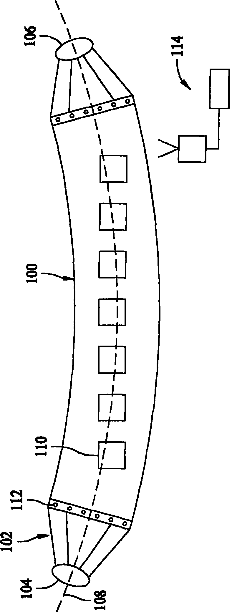
[0018] figure 1 is a side perspective view of an exemplary workpiece 100 that can be fabricated using the methods described herein. In the exem...


PUM


Abstract

Methods and systems for fabricating a composite structure are provided. The method (400, 500, 600) includes receiving data representing a portion of a surface (312) of the structure, measuring a surface of the structure, the measured surface corresponding to the received surface wherein the measuring is performed with the structure in a flexed condition, and determining a difference in a first and a second direction between the measured surface and the received surface at areas that correspond to the measured surface. The method also includes determining a difference in a third direction, transmitting to a morphing algorithm the determined differences in the first, second, and third directions, and determining a position in the first, second, and third directions of a point on the surface in the flexed condition that corresponds to a respective point on the received surface when the structure is placed in the nominal condition.

Description

technical field [0001] Embodiments of the present disclosure relate generally to methods and systems for manufacturing large components, and more particularly to methods and systems for forming close tolerance composite structures. Background technique [0002] Fabrication techniques for assembling large composite structures use massive tooling to provide a stable platform on which to form the structure. Definitive fit (DA) holes or other marker features are used to fix the structural position relative to a reference point. DA holes allow for accurate determination of the position of any point on the surface of the structure. Such precise positioning may be required when implementing further manufacturing processes on the structure after the initial forming process. Further processing here may include cutting apertures at predetermined locations or milling certain features into the surface of the structure. However, heavy tools may introduce a certain amount of sag into t...

Claims


Application Information

Patent Timeline
Patent Type & Authority Applications(China)
IPC IPC(8): B64F5/00
CPCG01B21/20
Inventor B·J·马什S·H·尼科尔斯
Owner THE BOEING CO
Why Eureka
Try Eureka