Lifting hook

A hook and rod technology, applied in the field of hooks, can solve the problems of being difficult to move away, affecting work efficiency, difficult to pull, and steel coils, etc.

Inactive Publication Date: 2011-03-09
CHANGSHU CABLE WORKS
View PDF7 Cites 10 Cited by
  • Summary
  • Abstract
  • Description
  • Claims
  • Application Information

AI Technical Summary

Problems solved by technology

[0003] But in published patent and non-patent literature, do not see the hook that is suitable for hoisting the coiled steel strip and has a simple structure. Taking the wire and cable manufacturer as an example, the steel strip is used as the armor of the wire and cable. Layer, before use, first hoist the steel coil, cut off the binding belt (steel belt) bound on the steel coil to prevent the steel coil from unwinding, and then place it on the tensioning device, and the tensioning device tightens the coil, And flatten the corresponding two sides of the steel coil, and finally transfer to the wire and cable production line
[0004] Due to the particularity of the shape of the steel coil, the known scale hook-shaped hook is difficult to pull into the central hole of the steel coil, and there is a risk of falling off, especially when the steel coil that was previously in a vertical state is placed on the coil tightening device On the working platform, the hook is pressed by the steel coil and it is difficult to remove it. It is necessary for the online operator to use tools to pry the steel coil to a degree sufficient to remove the hook, which not only increases the work level of the operator, but also Affect work efficiency

Method used


Image

  • Lifting hook
  • Lifting hook
  • Lifting hook

Examples


Embodiment

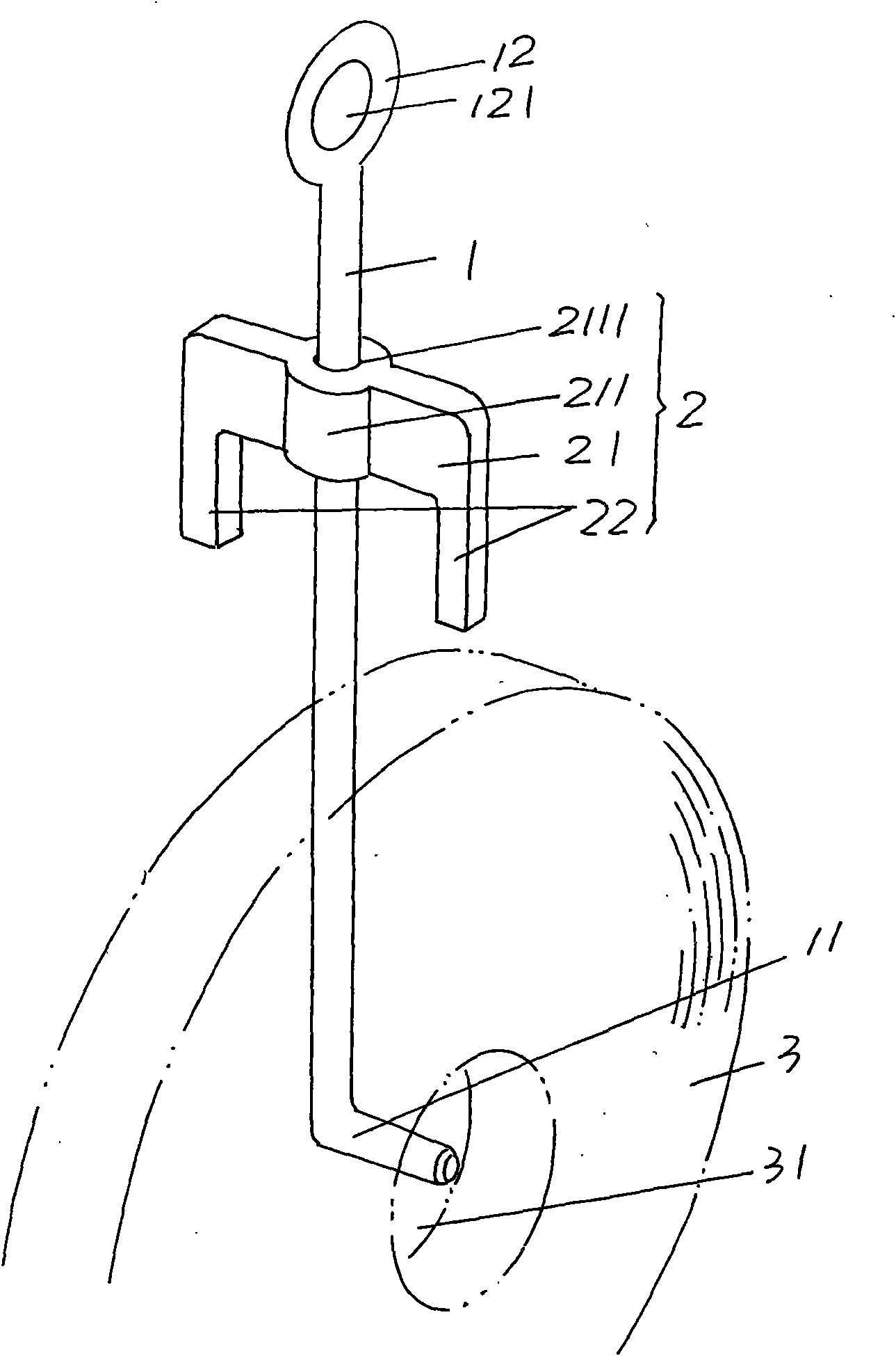
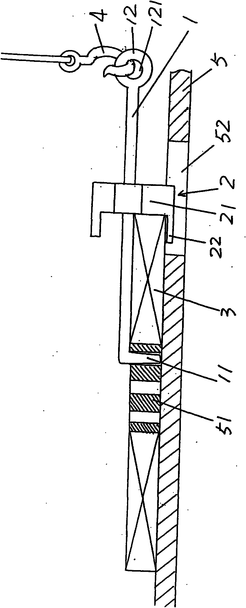
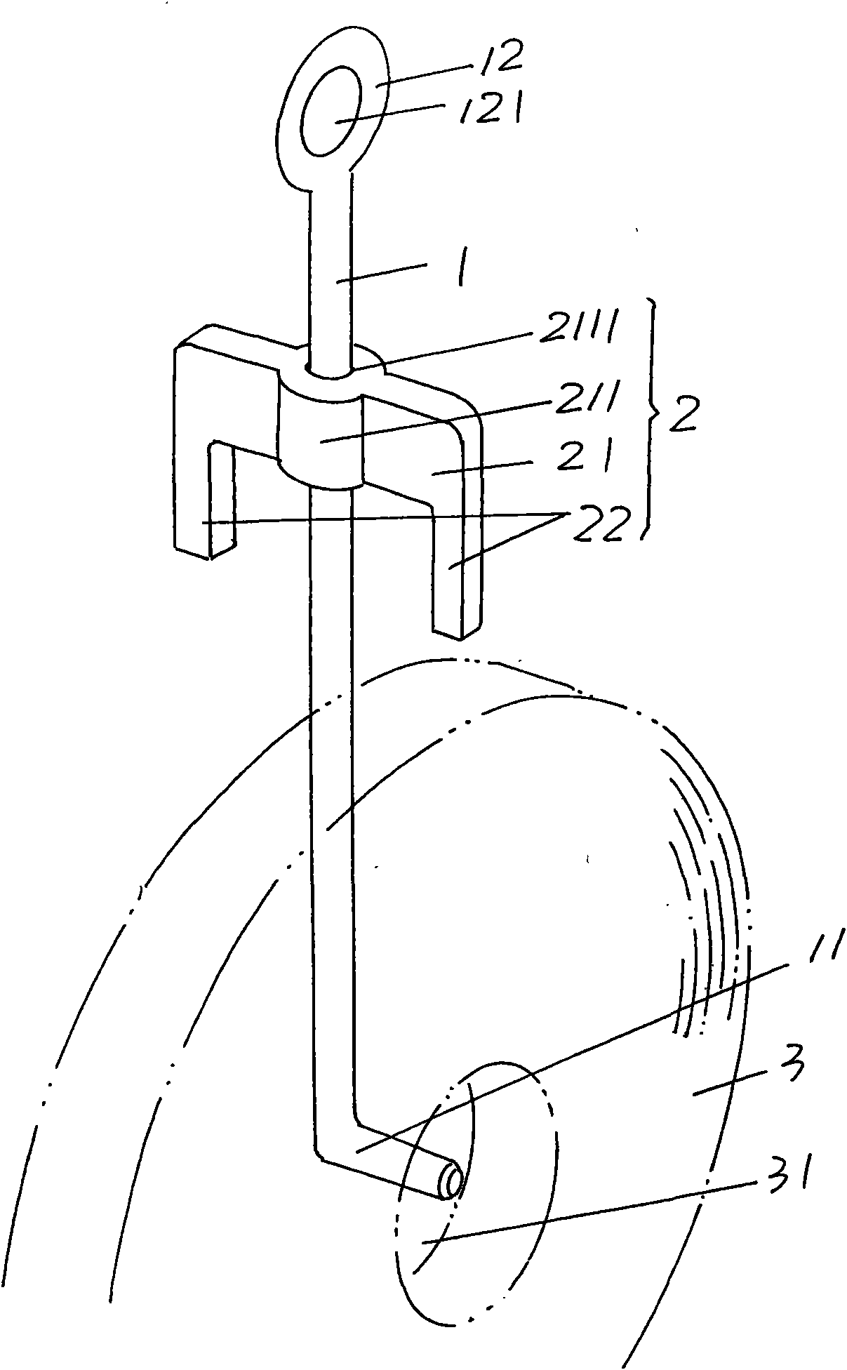
[0013] please see figure 1 , in order to facilitate public understanding, the applicant in figure 1 The steel coil 3 is shown in , and the center of the steel coil 3 has a central through hole 31 . The suspension hook provided by the present invention includes a suspender 1, which is made of metal material, and a pull claw 11 is formed by bending toward one side at the lower end of the hanger 1, and the pull claw 11 is formed with the suspension rod 1. Vertical, that is, it forms a 90° relationship with the boom 1, and a suspension ring 12 is formed at the upper end of the boom 1; As a preferred structure of the stop pawl 2, it includes a cross arm 21 and a pair of longitudinal arms 22, a cross arm sleeve 211 is formed at the center of the length direction of the cross arm 21, and a through hole 2111 is formed on the cross arm sleeve 211. , the transverse arm 2 is sleeved on the boom 1 through the through hole 2111. Since there are a pair of longitudinal arms 22, one of the ...


PUM


Abstract

The invention relates to a lifting hook, belonging to the technical field of lifting devices. The lifting hook comprises a lifting rod and a limiting claw, wherein a pulling claw to be pulled into a central hole of a coil of strip is formed at the lower end of the lifting rod, and a lifting ring for connecting with a lifting device is formed at the upper end of the lifting rod; and the limiting claw is used for limiting the coil of strip and is sleeved on the lifting rod in a sliding mode. The invention has the advantages that in the technical scheme, the pulling claw can be pulled into the central through hole of the coil of strip, and the limiting claw limits the coil of strip; because the limiting claw is arranged on the lifting rod in a sliding mode, the limiting claw can be adaptable to the radius change of the coil of strip; and due to the action of the limiting claw, the coil of strip can be conveniently put on an action platform on side, and the pulling claw can be conveniently retracted from the central hole of the coil of strip, thereby reducing the working strength of the on-line operating personnel and improving the lifting operation efficiency.

Description

technical field [0001] The invention belongs to the technical field of hoisting appliances, and in particular relates to a hook used for hoisting a steel belt reel. Background technique [0002] As the hook of the lifting device, there is no shortage of references in patent documents, especially Chinese patent documents. For example, the invention patent application publication number CN101759093A recommends a kind of hook, which is suitable for the lifting of pipes, and can avoid Deformation of the nozzle of the pipe. Also, Patent Application Publication No. CN101580204A discloses a spring hook for hoisting round objects, which adopts a four-bar linkage to control the opening and closing of a pair of clasping rings, and a pair of clasping rings facing each other One side is fixed with a non-slip rubber sleeve, which not only plays an anti-skid role, but also prevents damage to the metal objects being lifted. And, the invention patent application publication number CN10174...

Claims


Application Information

Patent Timeline
Patent Type & Authority Applications(China)
IPC IPC(8): B66C1/36
Inventor 陆超英陆康林
Owner CHANGSHU CABLE WORKS
Why Eureka
Try Eureka