Fuel cell gas diffusion layer structure and processing method thereof
A gas diffusion layer and fuel cell technology, applied in the direction of electrical components, battery electrodes, structural parts, etc., can solve the problems of unfavorable large-scale commercialization, long time consumption, cumbersome processing technology, etc., and achieve the benefit of reactant gas flow wetting , reduce the amount of water, increase the effect of specific surface area
- Summary
- Abstract
- Description
- Claims
- Application Information
AI Technical Summary
Problems solved by technology
Method used
Image
Examples
Embodiment 1
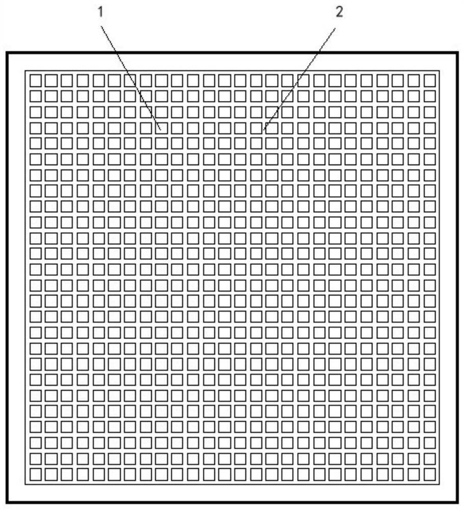
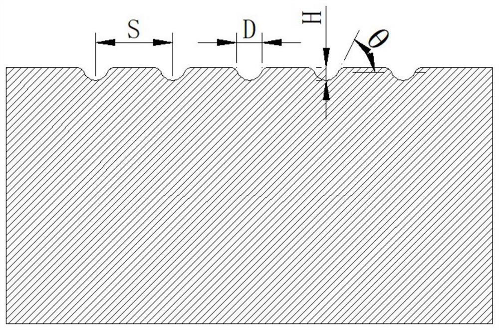
[0036] Such as figure 1 with 2 As shown, in the fuel cell gas diffusion layer structure of the present invention, the gas diffusion layer 1 is the base layer on the side close to the bipolar plate, and the surface of the gas diffusion layer 1 is provided with a number of groove textures 2 interlaced and connected to each other. A plurality of interconnected groove textures 2 divide the surface of the gas diffusion layer 1 into grids, which are used to eliminate the phenomenon of electrode flooding. A plurality of groove textures 2 that are interlinked with each other include groove textures that are parallel or nearly parallel to the flow direction, and groove textures that are perpendicular to the flow direction. In Example 1, the groove texture parallel to the flow direction and the groove texture perpendicular to the flow direction have the same cross-sectional area. The material of the base layer of the gas diffusion layer 1 is carbon black paper, and the specific dimens...
Embodiment 2
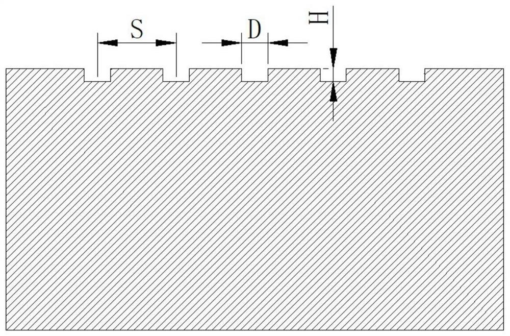
[0039] Such as figure 1 with 3 As shown, in the fuel cell gas diffusion layer structure of the present invention, the material of the base layer of the gas diffusion layer 1 is carbon fiber, and the cross-sectional shape of the groove texture 2 is rectangular; the specific dimensions are: length 30mm, width 30mm, thickness 1mm. The specific dimensions of the groove texture 2 are: the depth of the groove texture 2 is H=20 μm, the distance between adjacent groove textures 2 is S=500 μm, and the cross-sectional area of the groove texture parallel to the flow direction is larger than that of the groove perpendicular to the flow direction For the cross-sectional area of the texture, the width D of the groove texture perpendicular to the flow direction is 100 μm, and the width of the groove texture parallel to the flow direction is 1.5D. The groove texture 2 accounts for 47.98% of the surface area of the entire gas diffusion layer base layer. The groove structure on the surf...
Embodiment 3
[0042] Such as figure 1 , 4 As shown in and 5, in the fuel cell gas diffusion layer structure of the present invention, the material of the base layer of the gas diffusion layer 1 is carbon fiber, and the cross-sectional shape of the groove texture 2 is trapezoidal; the specific dimensions of the gas diffusion layer 1 are: length 50mm, width 50mm, 1.5mm thick. The specific size of trapezoidal groove texture 2 is: trapezoidal groove texture 2 width D 上底 =50μm, D 下底 = 30 μm, the depth H of the groove texture 2 = 30 μm, and the distance S between adjacent groove textures 2 = 250 μm. The cross-sectional area of the groove texture 2 along the flow direction expands gradually and then tapers along with the flow direction. The cross-sectional area at both ends of the groove texture 2 along the flow direction changes gradually, and the cross-sectional area in the middle of the groove texture 2 along the flow direction remains constant; the cross-sectional area in the middle of t...
PUM
| Property | Measurement | Unit |
|---|---|---|
| width | aaaaa | aaaaa |
| depth | aaaaa | aaaaa |
Abstract
Description
Claims
Application Information
 - R&D
- Intellectual Property
- Life Sciences
- Materials
- Tech Scout
- Unparalleled Data Quality
- Higher Quality Content
- 60% Fewer Hallucinations
Browse by: Latest US Patents, China's latest patents, Technical Efficacy Thesaurus, Application Domain, Technology Topic, Popular Technical Reports.
© 2025 PatSnap. All rights reserved.Legal|Privacy policy|Modern Slavery Act Transparency Statement|Sitemap|About US| Contact US: help@patsnap.com


