
Mounting structure for accumulator devices in electric vehicle

A technology for electric storage devices and electric vehicles, which is applied in the direction of electric power devices, combined cooling arrangement of power devices, electric vehicle charging technology, etc., to achieve the effects of suppressing deterioration, high cooling effect, and improving cooling efficiency

Active Publication Date: 2013-06-05
KAWASAKI MOTORS LTD
View PDF8 Cites 9 Cited by
  • Summary
  • Abstract
  • Description
  • Claims
  • Application Information

AI Technical Summary

Problems solved by technology

[0003] However, the energy density of secondary batteries is still several orders of magnitude lower than that of gasoline and other petroleum-based fuels. In order to ensure a practical driving distance, it is necessary to carry multiple batteries

Method used


Image

  • Mounting structure for accumulator devices in electric vehicle
  • Mounting structure for accumulator devices in electric vehicle
  • Mounting structure for accumulator devices in electric vehicle

Examples


Embodiment Construction

[0041] Embodiments according to the present invention will be described below with reference to the drawings. In addition, the direction concept used in the following description is based on the direction seen by the driver riding the electric motorcycle.

[0042] (first embodiment)

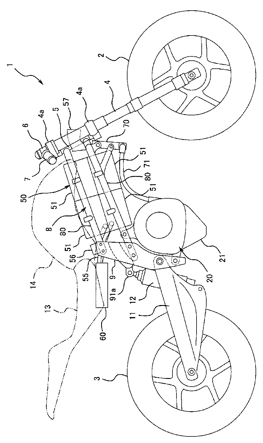
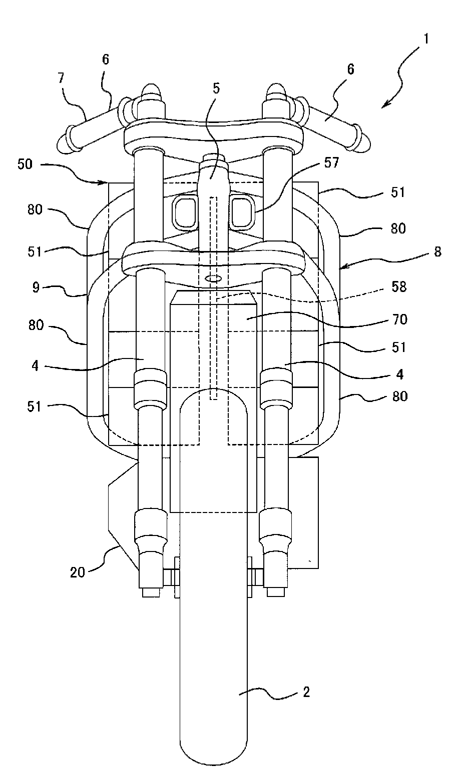
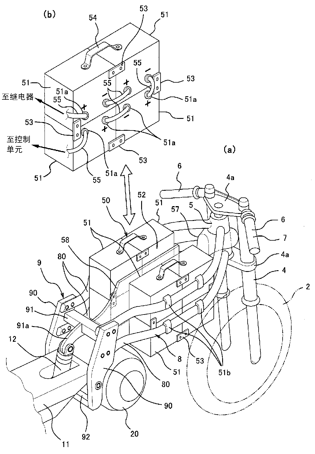
[0043] figure 1 It is a right side view showing main components such as a body frame, wheels, power equipment, batteries, etc. of the electric motorcycle 1 (electric vehicle) according to the first embodiment of the present invention, figure 2 for its main view. image 3 It is a perspective view viewed obliquely from behind showing a mounting structure for mounting a battery on a vehicle body, Figure 4 for its top view.

[0044] Such as figure 1As shown, the electric motorcycle 1 includes a front wheel 2 as a steering wheel and a rear wheel 3 as a driving wheel. The front wheel 2 is rotatably supported by the lower ends of a pair of left and right front forks 4 extending roughly in the ve...


PUM


Abstract

When mounting a plurality of batteries or other accumulator devices (51) on an electric two-wheeled vehicle (1) or the like, a group of accumulator devices (50) comprising the plurality of accumulator devices (51) has formed thereupon a passage for airflow created by vehicle motion (52) in a front-rear direction, through which passes the airflow created by the motion of the electric vehicle (1). Then, connection terminals (51a) of each accumulator device (51) and cables (55) connecting these terminals are positioned in this passage for airflow created by vehicle motion (52). By adopting this configuration, it is possible to effectively cool the accumulator devices (51), the connection terminals (51a) thereof, and the electric cables (55). The plurality of accumulator devices (51) are separated into two modules; left and right sides, and each module may be integrally connected and detachably mounted to the electric vehicle (1).

Description

technical field [0001] The present invention relates to a mounting structure of a power storage device in an electric vehicle such as an electric automobile, an electric motorcycle, or a hybrid automobile. Background technique [0002] In recent years, due to increasing environmental awareness and considering the depletion of oil resources in the future, there has been a greater demand than ever to reduce the fuel consumption of automobiles and motorcycles. On the other hand, lithium-ion secondary batteries represented by lithium-ion batteries have made great progress, and attempts to electrify driving power such as electric vehicles and hybrid vehicles are prevailing. [0003] However, the energy density of secondary batteries is still several orders of magnitude lower than that of gasoline and other petroleum-based fuels. In order to ensure a practical driving distance, multiple batteries need to be installed. In this regard, various efforts have been made on the battery ...

Claims


Application Information

Patent Timeline
Patent Type & Authority Applications(China)
IPC IPC(8): B60K11/06B60K1/04B60L11/18B62J9/00B62J99/00
CPCB60K11/02B60K2001/0466B62M7/04Y02T10/7055B60K11/04B60Y2200/12B60K1/04B62K2208/00Y02T10/7005B60L11/1877B60K2001/005B60K2001/006B62K2204/00Y02T10/705B62K11/04B60K11/06B60L3/0069B60L2200/12B60L2210/10B60L2240/36Y02T10/7072B60L50/51B60L53/80B60L58/21B60L58/26B60L50/66B60L50/64Y02T10/70Y02T10/72B62J43/28B62J43/16B62J50/30Y02T90/14Y02T90/12
Inventor 松田义基
Owner KAWASAKI MOTORS LTD
Learn More