
Link fault positioning method and system of packet transport network (PTN)

A technology for packet transmission network and link faults, applied in the field of communications, can solve problems such as undetectable blank areas, and achieve the effect of accurate and fast fault location.

Active Publication Date: 2015-01-28
深圳市中兴通讯技术服务有限责任公司
View PDF6 Cites 0 Cited by
  • Summary
  • Abstract
  • Description
  • Claims
  • Application Information

AI Technical Summary

Problems solved by technology

[0016] The main purpose of the present invention is to provide a method and system for locating link faults in a packet transport network, so as to at least solve the above-mentioned problem of undetectable blank areas in the prior art

Method used


Image

  • Link fault positioning method and system of packet transport network (PTN)
  • Link fault positioning method and system of packet transport network (PTN)
  • Link fault positioning method and system of packet transport network (PTN)

Examples


Embodiment 1

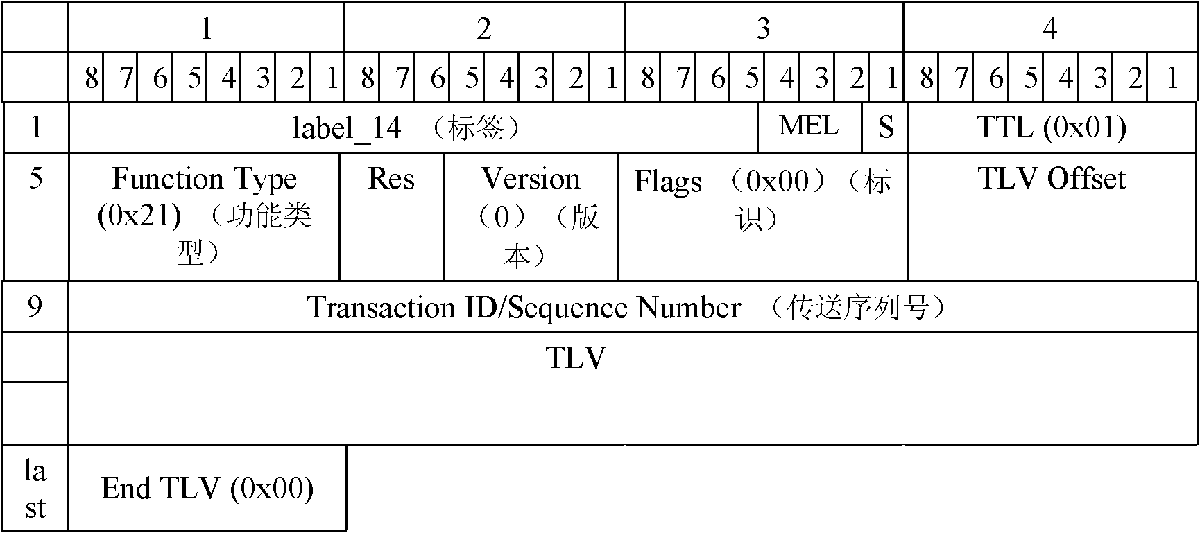
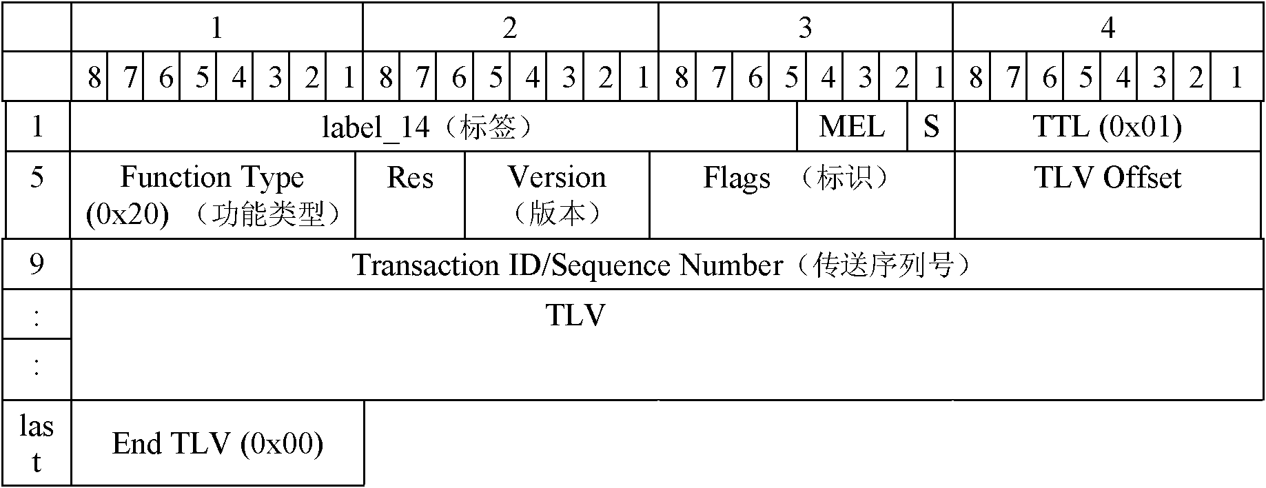
[0051] This embodiment describes in detail the link fault location process in practical applications, Figure 6 shows a schematic diagram of the faulty link location structure of this embodiment, as Figure 6 As shown, the link includes nodes A, B, C, ... N, N+1, Y, where node A and node Y are endpoints, and the rest of the nodes are intermediate nodes on the link. Between node N and node N A connectivity failure occurred on the link between +1. The connectivity fault location process on this link is as follows: Figure 7 shown, including the following steps:

[0052] Step S702, configure the connectivity detection between end-to-end services, that is, configure node OAM on node A and node Y, the configuration process is the same as the OAM configuration in T-MPLS / MPLS-TP described in the background technology section, That is, the MEGIDs of node A and node Y are the same, and the MEP IDs of node A and node Y are each other's peer MEP ID; the specific configuration process ...


PUM


Abstract

The invention discloses a link fault positioning method and system of a packet transport network (PTN). The method comprises the following steps: when a first business end detects the condition that a connectivity fault appears in a link between the first business end and a second business end, automatically triggering fault positioning, and sending a loopback message to the second business end along the a faulty link; when an intermediate node positioned on the faulty link receives the loopback message, forwarding the loopback message to the next node, and sending a loopback response message to the first business end along a path opposite to the path of receiving the loopback message; and positioning the position of the fault in the faulty link by the first business end according to the received loopback response message. In the invention, by automatically triggering the device after the fault is detected, a series of configurations required for manually positioning the fault are avoided, thereby being suitable for quickly positioning the fault; and by sending the loopback message, the connectivity of the link is cheked section by section and the faulty section is investigated from the returned loopback response message, thereby realizing the purpose of accurately positioning the fault.

Description

technical field [0001] The present invention relates to the communication field, in particular to a link fault location method and system of a packet transmission network. Background technique [0002] In the increasingly competitive market environment, operators' networks and services have begun to evolve towards packetization. Based on the trust and operation experience of the existing SDH transport network (Synchronous Digital Hierarchy, Synchronous Digital System), the most important requirement of operators for the packet transport network is: easy maintenance and management, to reduce the need for manual on-site operations, and reduce Requirements for maintenance and management personnel. Therefore, a powerful OAM (Operations Administration and Maintenance, operation, maintenance and management) mechanism is defined in the existing packet transport network. [0003] In the existing packet transmission network, end-to-end fault detection is defined. Confirm the conne...

Claims


Application Information

Patent Timeline
Patent Type & Authority Patents(China)
IPC IPC(8): H04L12/24H04L12/26
Inventor 汤跃娟
Owner 深圳市中兴通讯技术服务有限责任公司
Learn More