Suction port body and electric dust collector with the same

A vacuum cleaner and suction port technology, applied in the field of electric vacuum cleaners and their suction port bodies, can solve the problems of reduced visibility, reduced display area, reduced appearance design, etc., and achieves good visibility, miniaturization, and excellent design. Effect

Inactive Publication Date: 2011-03-23
HITACHI APPLIANCES INC
View PDF5 Cites 9 Cited by
  • Summary
  • Abstract
  • Description
  • Claims
  • Application Information

AI Technical Summary

Problems solved by technology

However, according to this conventional example, the number of parts increases
Moreover, if it is provided only on one side, not only will the display area be reduced to reduce visibility, but also it will become an asymmetrical design biased to one side, which may reduce the designability.

Method used


Image

  • Suction port body and electric dust collector with the same
  • Suction port body and electric dust collector with the same
  • Suction port body and electric dust collector with the same

Examples


no. 1 example

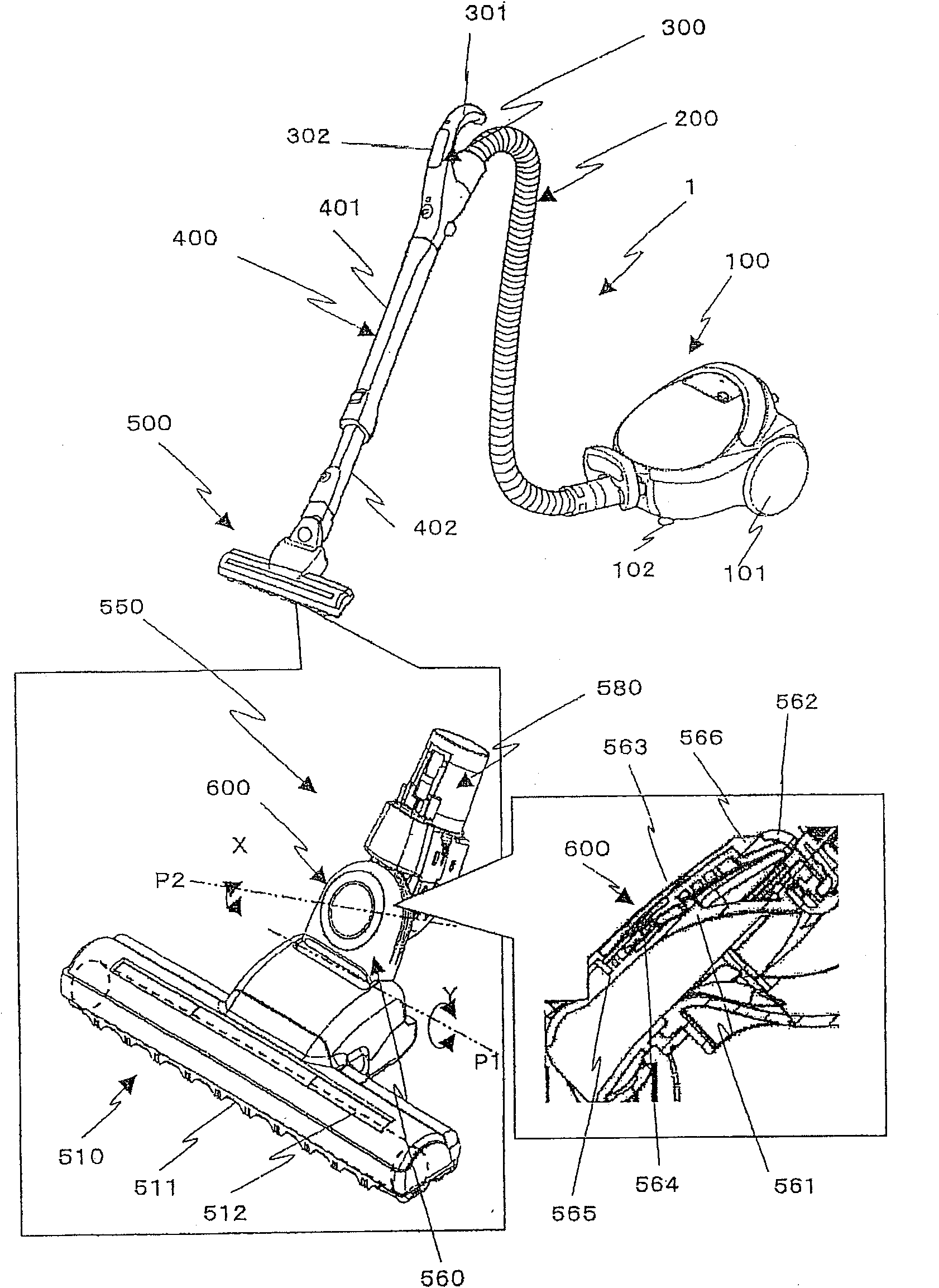
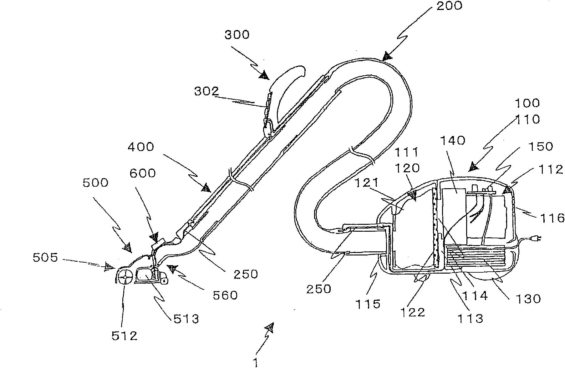
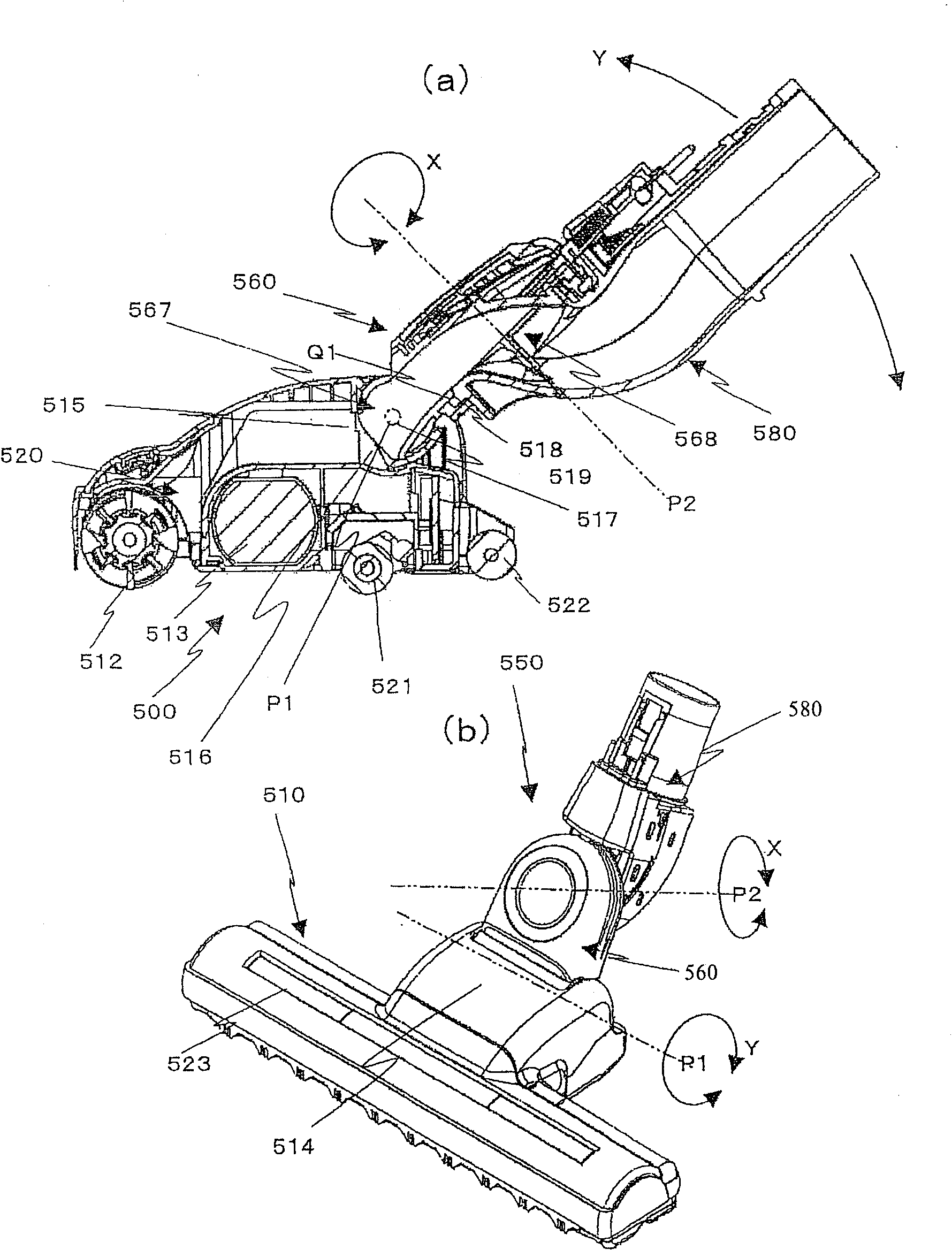
[0038] Figure 1 to Figure 5 The electric vacuum cleaner of the first embodiment is shown. here, figure 1 is a schematic diagram of the electric vacuum cleaner of the first embodiment. figure 2 is the internal structure of the electric vacuum cleaner of the first embodiment. image 3 is a structural diagram of the mouthpiece body of the first embodiment, image 3 (a) is a central longitudinal sectional view, image 3 (b) is an external perspective view. Figure 4 It is a component development view of the lower arm part of the mouthpiece body of the first embodiment. Figure 5 is a schematic diagram of the display device of the mouthpiece body of the first embodiment, Figure 5 (a) is a block diagram of the operation state display unit, Figure 5 (b) is a reflection path diagram. Image 6 It is a use state diagram of the electric vacuum cleaner of the first embodiment.

[0039] First, refer to figure 1 , the schematic structure of the electric vacuum cleaner of this ...

no. 2 example

[0091] Next, refer to Figure 7 , to illustrate the mouthpiece body 501 of the second embodiment. The free connection portion 550a of the mouthpiece body 501 has the following structure, including a tubular lower arm portion 560a and a tubular upper arm portion 580a, the lower arm portion 560a rotates in the horizontal direction X, and the upper arm portion 580a rotates in the vertical direction Y.

[0092] That is, the lower arm portion 560a of the freely connecting portion 550a has a structure in which one end in the longitudinal direction is rotatably connected to the upper arm portion 580a through the horizontal rotation axis P1 arranged parallel to the longitudinal direction of the mouthpiece body 510, and the other end is The mouthpiece main body 510 is rotatably connected via a vertical rotation axis P2 perpendicular to the horizontal rotation axis P1.

[0093] Specifically, a vertical rotation axis P2 perpendicular to the longitudinal direction is formed behind the ce...

no. 3 example

[0097] Next, refer to Figure 8 to Figure 13 , the mouthpiece body of the third embodiment will be described. Figure 9 An exploded perspective view showing the mouthpiece body 10 of the third embodiment. exist Figure 9 Among them, the reference numeral 11 is the lower case of the mouthpiece main body 10A, the reference number 12 is the upper case of the mouthpiece main body 10A arranged above the lower case 11, and the reference numeral 212 is composed of the upper case 12 and the lower case. 11 constitutes a rotating cleaning body accommodation chamber, reference numeral 204 is a rotating cleaning body disposed in the rotating cleaning body accommodation chamber 212, reference numeral 205 is a motor for driving the rotating cleaning body 204, and reference numeral 207 is a motor for lifting the cleaning body. A safety switch for automatically stopping rotation when the mouthpiece body 10 is closed, reference numeral 208 is a pulley on the motor side, reference numeral 209...


PUM


Abstract

The present invention provides a suction port body of a large-scale display device, which has excellent visibility and excellent appearance design, and also provides an electric dust collector with the suction port body. A free connection part (500) comprises a tubular lower arm (560) and a tubular upper arm (580). The lower arm connects one end in the length direction with a suction port body (510) rotatably through a first rotation shaft part, and the other end is rotatably connected with one end of the upper arm through a second rotation shaft part. The first rotation shaft part and the second rotation shaft part are provided with one member selected from a horizontal rotation shaft and a vertical rotation shaft which is orthogonal with the horizontal rotation shaft, wherein the horizontal rotation shaft is configured parallelly with the length direction of the suction port body. The lower arm or the upper arm which rotates through the horizontal rotation shaft relatively to suction port body is provided with the following components: a housing component which communicates without air leakage; and a display substrate which is configured between a cover component that covers the outside of the housing component and the housing component and is provided with a light source part, and the cover component is provided with a light guiding part which diffuses the light from the light source part.

Description

technical field [0001] The present invention relates to an electric vacuum cleaner and its nozzle body, and relates to a suction nozzle body provided with a display device for displaying an operating state and an operation mode, and an electric vacuum cleaner using the same. Background technique [0002] The current mainstream electric vacuum cleaner has a so-called canister type structure in which a vacuum cleaner body equipped with a dust collecting device and a floor suction nozzle body that sucks dust from the floor surface are connected by a suction pipe or a suction hose. The vacuum cleaner body of this conventional example is equipped with a dust collecting device and a blower device inside, and can move freely by wheels. On the other hand, the floor surface suction body is equipped with a rotary cleaning body and its drive unit in order to clean the floor surface, and by rotating the rotary cleaning body, the dust on the floor surface is fiddled and sucked. And this...

Claims


Application Information

Patent Timeline
Patent Type & Authority Applications(China)
IPC IPC(8): A47L9/02G09F9/00F21V8/00F21V19/00F21Y101/02
Inventor 梅泽功一大木雅之漆原笃彦仓田敦史佐藤繁则伊藤则和田中博文林正二
Owner HITACHI APPLIANCES INC
Why Eureka
Try Eureka