Suction port body and electric dust collector with same
A technology for vacuum cleaners and suction nozzles, which is applied in the field of electric vacuum cleaners and suction nozzles, can solve the problems of reduced visibility, reduced display area, and reduced appearance design, and achieves good visibility, miniaturization, and excellent appearance design. Effect
- Summary
- Abstract
- Description
- Claims
- Application Information
AI Technical Summary
Problems solved by technology
Method used
Image
Examples
no. 1 example
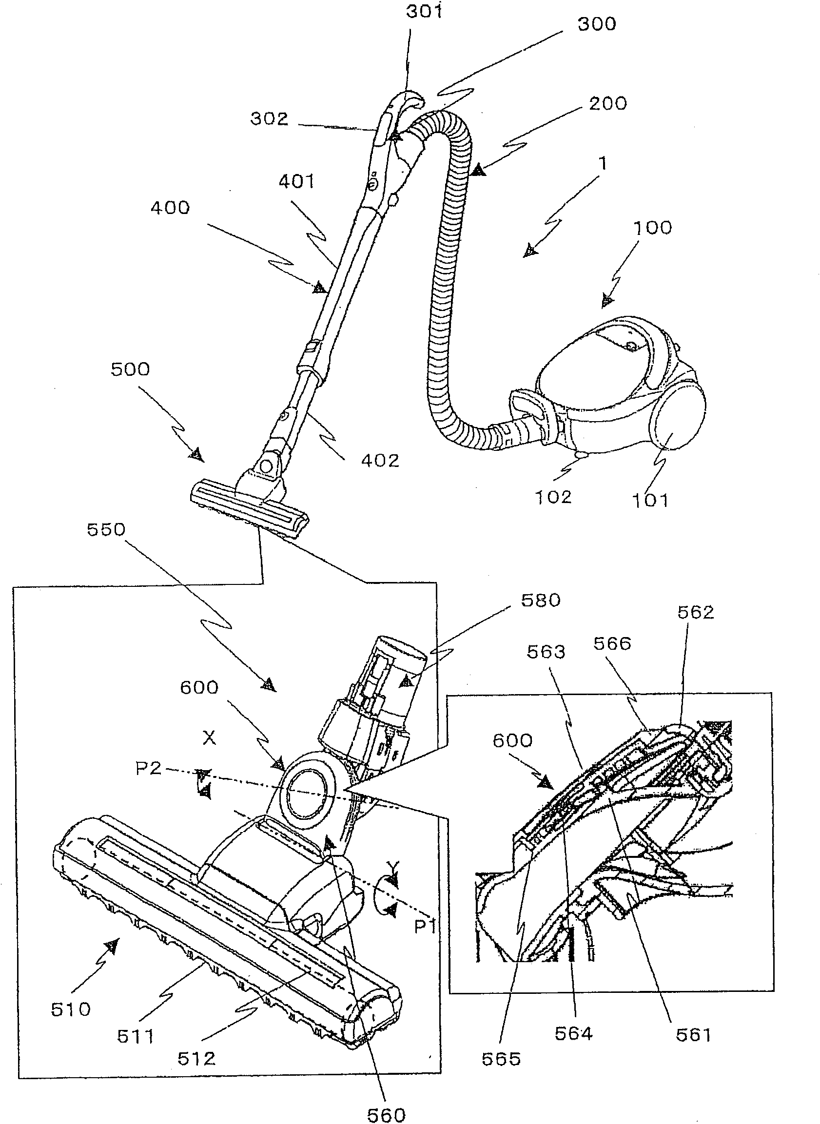
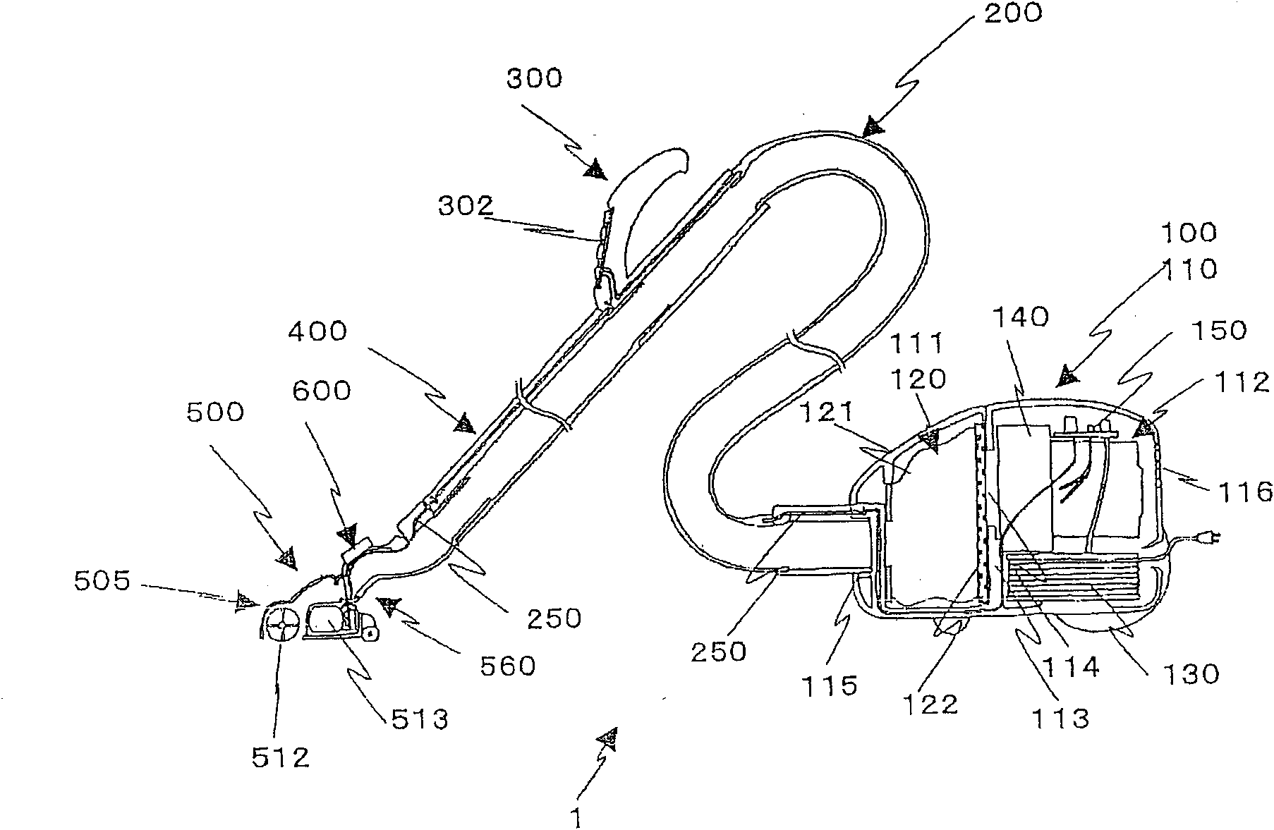
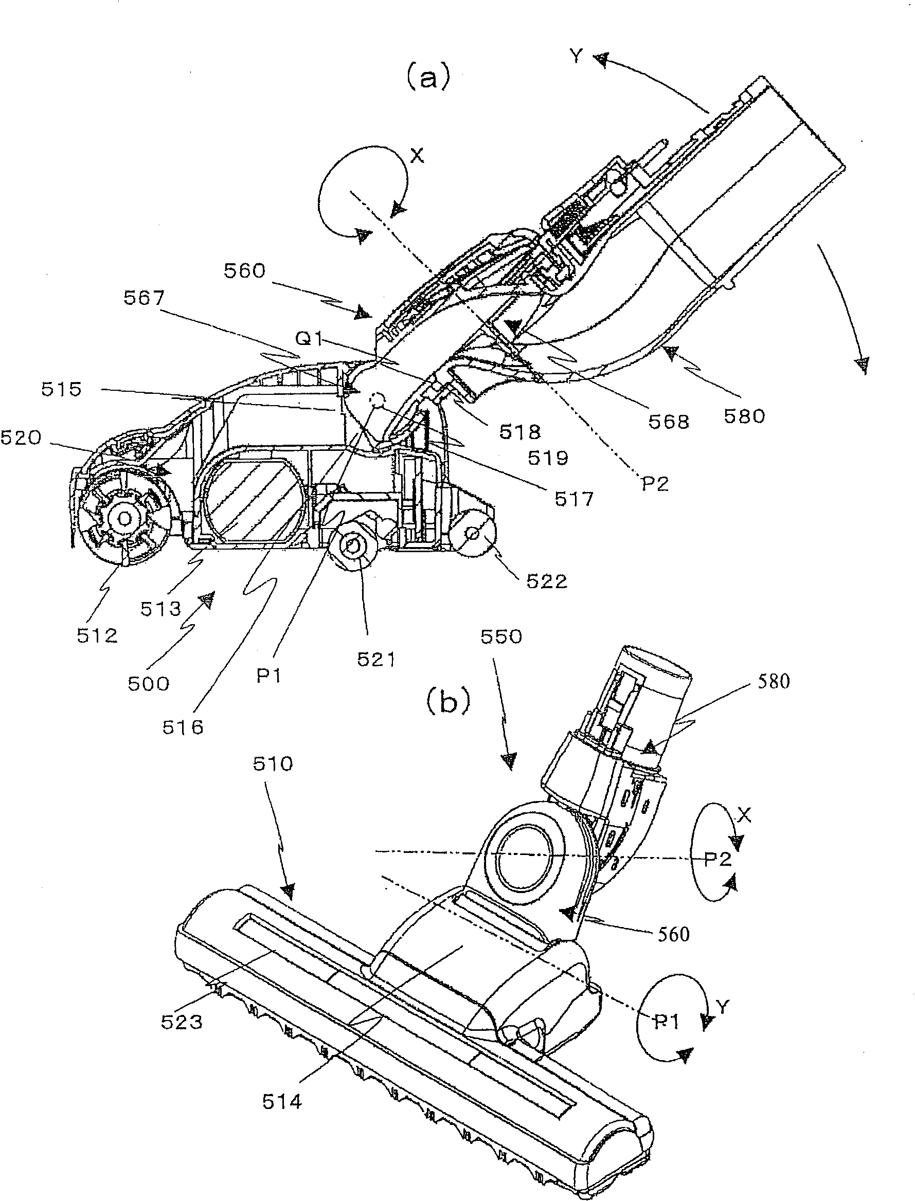
[0038] Figure 1 to Figure 5 The electric vacuum cleaner of the first embodiment is shown. here, figure 1 is a schematic diagram of the electric vacuum cleaner of the first embodiment. figure 2 is the internal structure of the electric vacuum cleaner of the first embodiment. image 3 is a structural diagram of the mouthpiece body of the first embodiment, image 3 (a) is a central longitudinal sectional view, image 3 (b) is an external perspective view. Figure 4 It is a component development view of the lower arm part of the mouthpiece body of the first embodiment. Figure 5 is a schematic diagram of the display device of the mouthpiece body of the first embodiment, Figure 5 (a) is a block diagram of the operation state display unit, Figure 5 (b) is a reflection path diagram. Figure 6 It is a use state diagram of the electric vacuum cleaner of the first embodiment.
[0039] First, refer to figure 1 , the schematic structure of the electric vacuum cleaner of this...
no. 2 example
[0091] Next, refer to Figure 7 , to illustrate the mouthpiece body 501 of the second embodiment. The free connection portion 550a of the mouthpiece body 501 has the following structure, including a tubular lower arm portion 560a and a tubular upper arm portion 580a, the lower arm portion 560a rotates in the horizontal direction X, and the upper arm portion 580a rotates in the vertical direction Y.
[0092] That is, the lower arm portion 560a of the freely connecting portion 550a has a structure in which one end in the longitudinal direction is rotatably connected to the upper arm portion 580a through the horizontal rotation axis P1 arranged parallel to the longitudinal direction of the mouthpiece body 510, and the other end is The mouthpiece main body 510 is rotatably connected via a vertical rotation axis P2 perpendicular to the horizontal rotation axis P1.
[0093] Specifically, a vertical rotation axis P2 perpendicular to the longitudinal direction is formed behind the ce...
no. 3 example
[0097] Next, refer to Figure 8 to Figure 13 , the mouthpiece body of the third embodiment will be described. Figure 9 An exploded perspective view showing the mouthpiece body 10 of the third embodiment. exist Figure 9 Among them, the reference numeral 11 is the lower case of the mouthpiece main body 10A, the reference number 12 is the upper case of the mouthpiece main body 10A arranged above the lower case 11, and the reference numeral 212 is composed of the upper case 12 and the lower case. 11 constitutes a rotating cleaning body accommodation chamber, reference numeral 204 is a rotating cleaning body disposed in the rotating cleaning body accommodation chamber 212, reference numeral 205 is a motor for driving the rotating cleaning body 204, and reference numeral 207 is a motor for lifting the cleaning body. A safety switch for automatically stopping rotation when the mouthpiece body 10 is closed, reference numeral 208 is a pulley on the motor side, reference numeral 209...
PUM
 Abstract
Description
Claims
Application Information
 - R&D
- Intellectual Property
- Life Sciences
- Materials
- Tech Scout
- Unparalleled Data Quality
- Higher Quality Content
- 60% Fewer Hallucinations
Browse by: Latest US Patents, China's latest patents, Technical Efficacy Thesaurus, Application Domain, Technology Topic, Popular Technical Reports.
© 2025 PatSnap. All rights reserved.Legal|Privacy policy|Modern Slavery Act Transparency Statement|Sitemap|About US| Contact US: help@patsnap.com


