High-low pressure buffer system

A buffer system, high and low pressure technology, applied in the field of buffer devices, can solve the problems of buffer cylinder design, slow movement, energy consumption and other problems

Active Publication Date: 2011-03-23
INDEX AUTOMATIC TECH
View PDF0 Cites 7 Cited by
  • Summary
  • Abstract
  • Description
  • Claims
  • Application Information

AI Technical Summary

Problems solved by technology

[0002] Generally, a buffer cylinder is installed at the lower end of the punching machine. Its function is to withstand the force of the upper stamping cylinder when it is pressed down. However, the buffer cylinder has always had a problem that the moving speed and pressure cannot be combined.
Generally, the moving speed is slow at high pressure, and the faster the moving speed, the lower the pressure. This problem has long plagued the design of buffer cylinders. How to achieve both is a problem to be solved.
The second problem is that since the buffer cylinder will continue to pressurize, decompress, or inflate and exhaust in conjunction with the action of the punch, it is necessary to have an external pressure source to continuously provide pressure. , in other words, it will continue to consume energy, which is also a problem for the industry

Method used


Image

  • High-low pressure buffer system
  • High-low pressure buffer system
  • High-low pressure buffer system

Examples


Embodiment Construction

[0015] The structure, characteristics and effects of the present invention will be described in detail by citing the following embodiments in conjunction with the accompanying drawings.

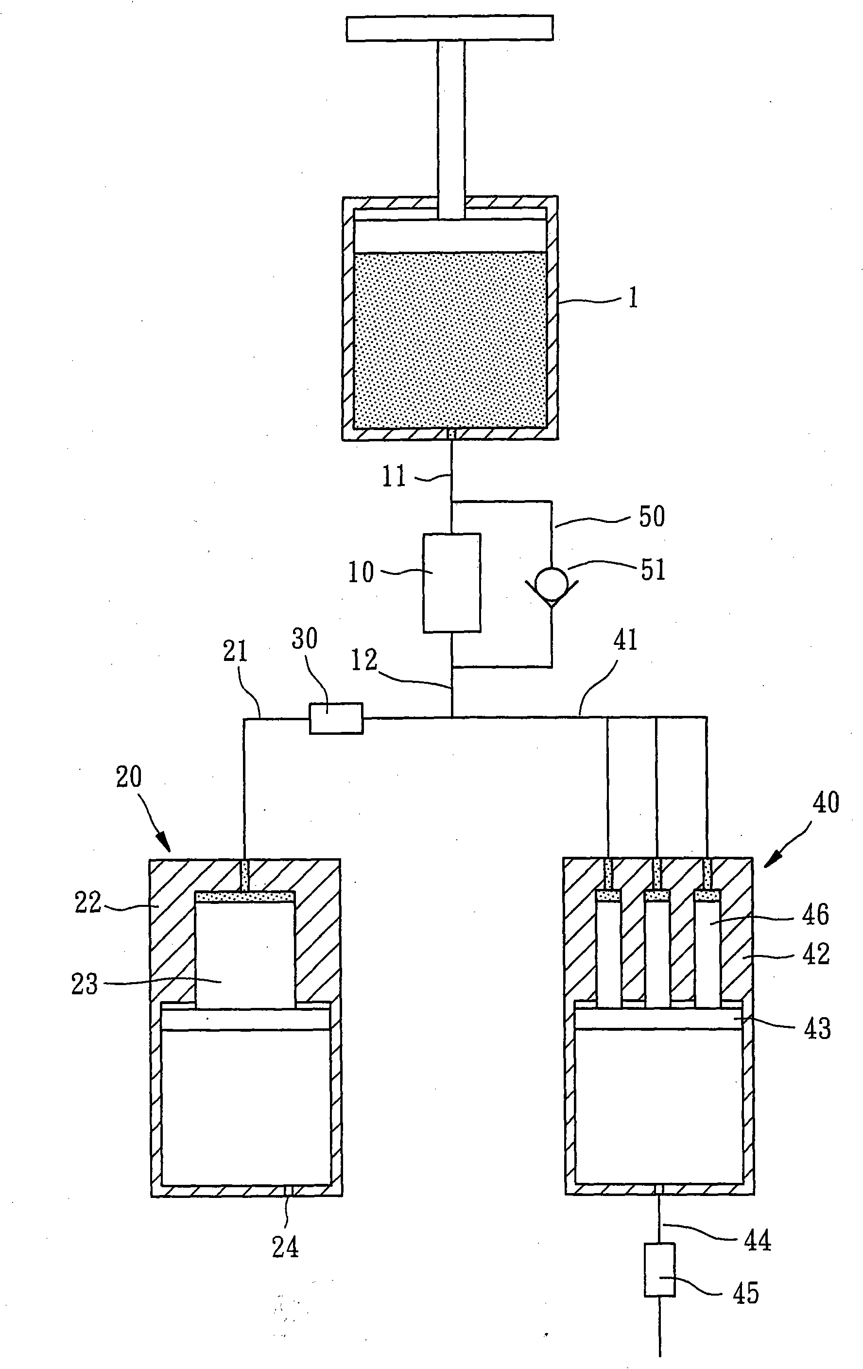
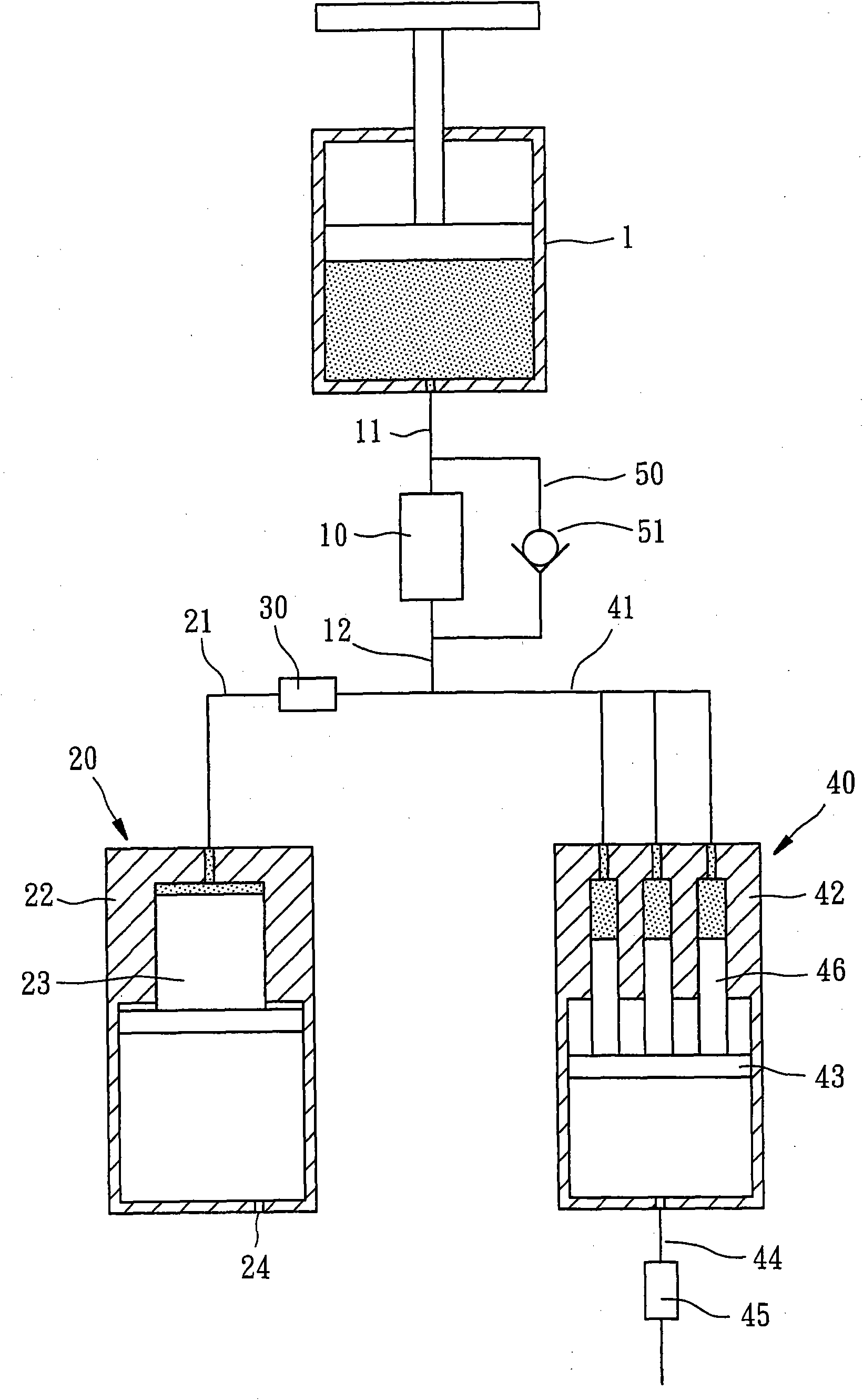
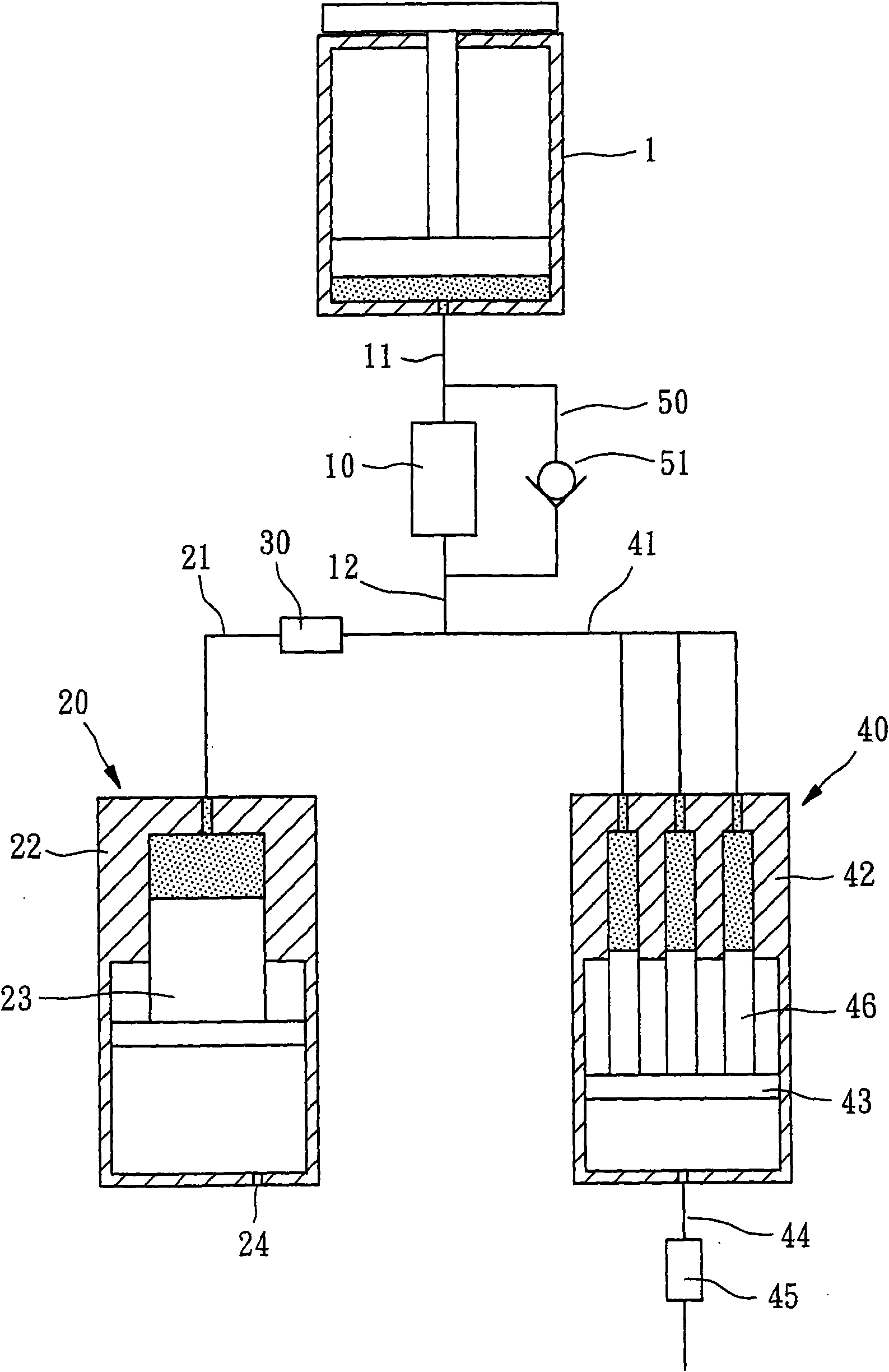
[0016] First, if Figure 1 ~ Figure 4 As shown, the high and low pressure buffer system of the present invention is used to connect with the buffer cylinder 1 of the general press machine. The high and low pressure buffer system of the present invention includes:

[0017] A pressure regulating valve 10, one end is connected to a front oil delivery pipe 11 and the other end is connected to a rear oil delivery pipe 12, the front oil delivery pipe 11 of the pressure regulating valve 10 communicates with the buffer cylinder 1 of the punch press, and the pressure regulating valve 10 can be adjusted to set and control the pressure value of the buffer cylinder 1 .

[0018] A low-pressure pneumatic cylinder 20 is connected to the rear oil delivery pipe 12 of the pressure regulating valve 10 with a f...


PUM


Abstract

The invention relates to a high-low pressure buffer system, connected with the buffering cylinder of a common punching machine. The high-low pressure buffer system comprises a pressure regulating valve, a low pressure pneumatic cylinder, an oil way switch, a high pressure pneumatic cylinder and an oil return pipeline; wherein the pressure regulating valve is communicated with the buffering cylinder of a punching machine; the low pressure pneumatic cylinder is connected with the pressure regulating valve by virtue of a first oil pressure pipeline, and the low pressure pneumatic cylinder is stored with gas; the oil way switch is arranged on an oil pressure pipeline between the low pressure pneumatic cylinder and the pressure regulating valve, so as to control the on and off of the oil pressure pipeline; the high pressure pneumatic cylinder is connected with the pressure regulating valve by virtue of a second oil pressure pipeline and is connected with an external gas supply device by virtue of another pipeline, and the pipeline is provided with an air suction/exhaust control switch; and the oil return pipeline is communicated with the front and rear oil pipelines of the pressure regulating valve, and the oil return pipeline is provided with a check valve, so that oil can flow to the buffering cylinder along the oil return pipeline and reverse non-return effect is realized.

Description

technical field [0001] The present invention relates to a buffer device used in a punch press, in particular to a high and low pressure buffer system. Background technique [0002] Generally, a buffer cylinder is arranged at the lower end of the punching machine, and its function is to withstand the force of the upper punching cylinder when it is pressed down. Generally, the moving speed is slow at high pressure, and the faster the moving speed, the lower the pressure. This problem has long plagued the design of the buffer cylinder. How to achieve both is a problem to be solved. The second problem is that since the buffer cylinder will continue to pressurize, decompress, or inflate and exhaust in conjunction with the action of the punch, it is necessary to have an external pressure source to continuously provide pressure. , In other words, it will continue to consume energy, which is also a problem for the industry. Contents of the invention [0003] In view of the above...

Claims


Application Information

Patent Timeline
Patent Type & Authority Applications(China)
IPC IPC(8): B21D22/02
Inventor 林瑞坤
Owner INDEX AUTOMATIC TECH
Why Eureka
Try Eureka