Supercharge Your Innovation With Domain-Expert AI Agents!

Optical encoder device

An encoding device and optical technology, which is applied in the direction of transmitting sensing components, measuring devices, and converting sensor output by using optical devices, can solve problems such as uncomfortable light patterns and achieve the effect of reducing distortion

Active Publication Date: 2011-03-23
SANYO DENKI CO LTD
View PDF11 Cites 5 Cited by
  • Summary
  • Abstract
  • Description
  • Claims
  • Application Information

AI Technical Summary

Problems solved by technology

[0017] In the technique described in Patent Document 3, the distortion rate becomes 0.79% by setting the number of slits to 8. However, in consideration of reducing the distortion rate beyond that, it is necessary to increase the number of slits to 16, 32, and 2 factorial, making it difficult to make designs that effectively use the light-receiving pattern long and so on

Method used


Image

  • Optical encoder device
  • Optical encoder device
  • Optical encoder device

Examples


Embodiment Construction

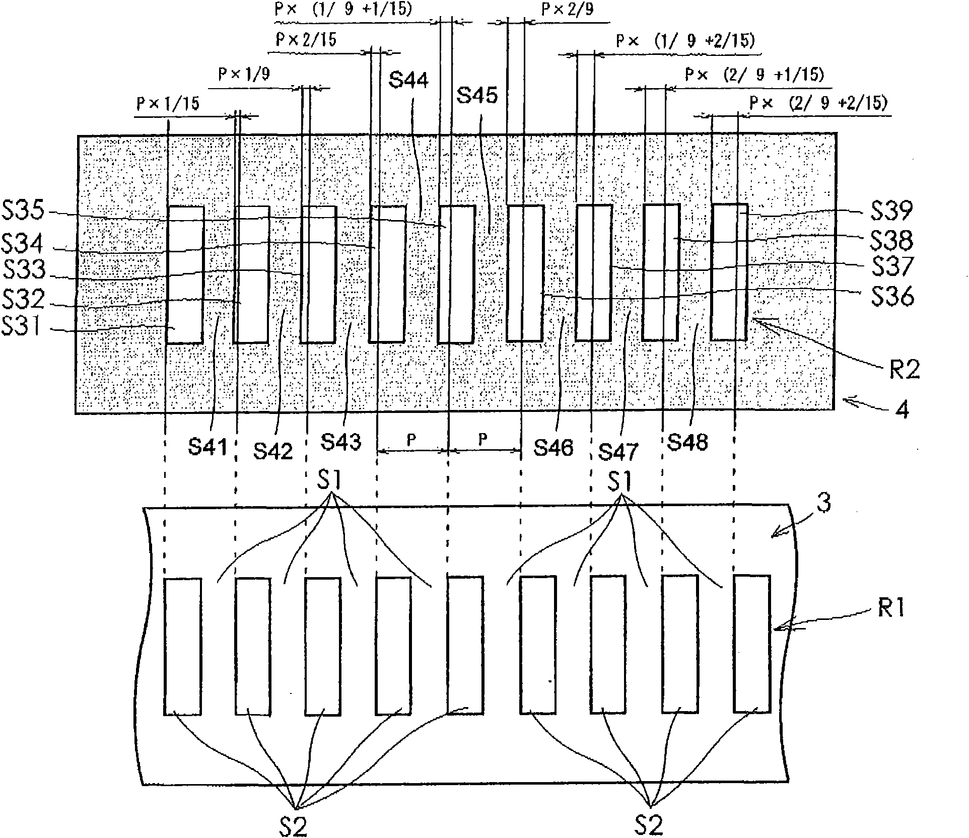
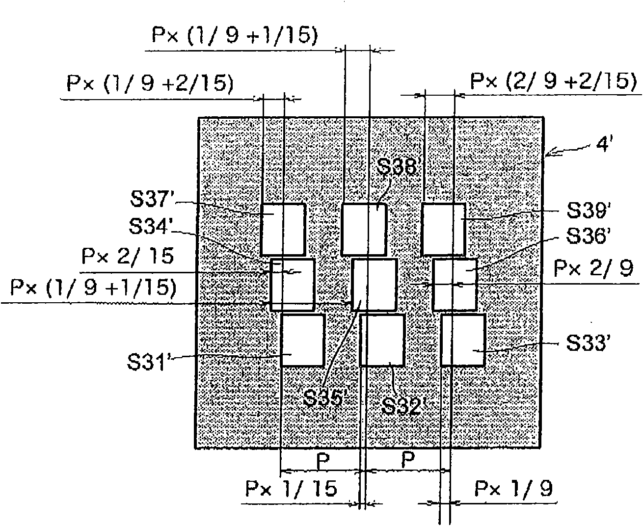
[0045] Hereinafter, embodiments of the optical encoder device of the present invention will be described in detail with reference to the drawings. figure 1 It is a series of perspective views schematically showing an embodiment in which the present invention is applied to a first transmissive optical encoder device. exist figure 1 Among them, the member indicated by reference numeral 1 is a light-emitting element composed of a light-emitting diode or the like, and the member indicated by reference numeral 2 is a light-receiving element composed of a semiconductor substrate having a function of converting an optical signal into an electrical signal and outputting it. Between the light-emitting element 1 and the light-receiving element (photoelectric conversion element) 2, a movable slit plate 3 and a fixed slit plate 4 fixed to an unillustrated fixing portion are arranged. In addition, in figure 1 In the present invention, the movable slit plate 3 is a rectangular plate, but ...


PUM


Abstract

The present invention provides an optical encoder device in which the number of slits formed in a stationary member or light receiving elements may be freely determined with little distortion. The number S of light transmissive slits which are formed in a stationary slit plate (4) satisfies a relationship: S=n*n' where n is an integer of 2 or more and n' is an integer of 2 or more except for a combination of n=2 and n'=2 and a combination of n=3 and n'=2, the value of a is an integer of 0<=a<=n-1, and the value of b is an integer of 0<=b<=n'-1. The plurality of light transmissive slits are formed in the stationary slit plate (4) such that when one of the light transmissive slits is optically coincident with one of the first light transmissive slits formed in the movable slit plate (3), the remaining S-1 second light transmissive slits are shifted in position from other first light transmissive slits corresponding to the remaining second light transmissive slits by S-1 phase differences represented by P*[a / (3*n)+b / (5*n')] where the value of a and the value of b are in different combinations.

Description

technical field [0001] The present invention relates to an optical encoder capable of obtaining an output signal with less distortion (distortion). Background technique [0002] Optical encoders are broadly classified into a transmission type that transmits light using a moving slit having a light-transmitting portion and a non-transmitting portion, and a reflective type that uses a moving slit that has a light-reflecting portion and a non-reflecting portion and reflects light. . Both transmissive and reflective optical encoders are provided with a light transmission part in such a way that the light irradiated on the light receiving element arranged to face the moving slit changes according to the displacement of the moving slit. An optical encoder with a fixed slit in the non-transmitting part, and an optical encoder in which a plurality of light-receiving elements are arranged so that the arrangement pattern of the plurality of light-receiving elements itself functions a...

Claims


Application Information

Patent Timeline
Patent Type & Authority Applications(China)
IPC IPC(8): G01D5/32
CPCG01D5/34707
Inventor 庄司祐大
Owner SANYO DENKI CO LTD
Features
  • R&D
  • Intellectual Property
  • Life Sciences
  • Materials
  • Tech Scout
  • Unparalleled Data Quality
  • Higher Quality Content
  • 60% Fewer Hallucinations
Learn More