
Capacitive touch panel

A capacitive touch and panel technology, which is applied in the input/output process of electrical digital data processing, instruments, and data processing, etc., can solve the problems of darkening of images, waste of materials, increase of manufacturing steps, etc., to reduce reflected light. Effect

Inactive Publication Date: 2011-03-23
RITFAST CORP
View PDF0 Cites 28 Cited by
  • Summary
  • Abstract
  • Description
  • Claims
  • Application Information

AI Technical Summary

Problems solved by technology

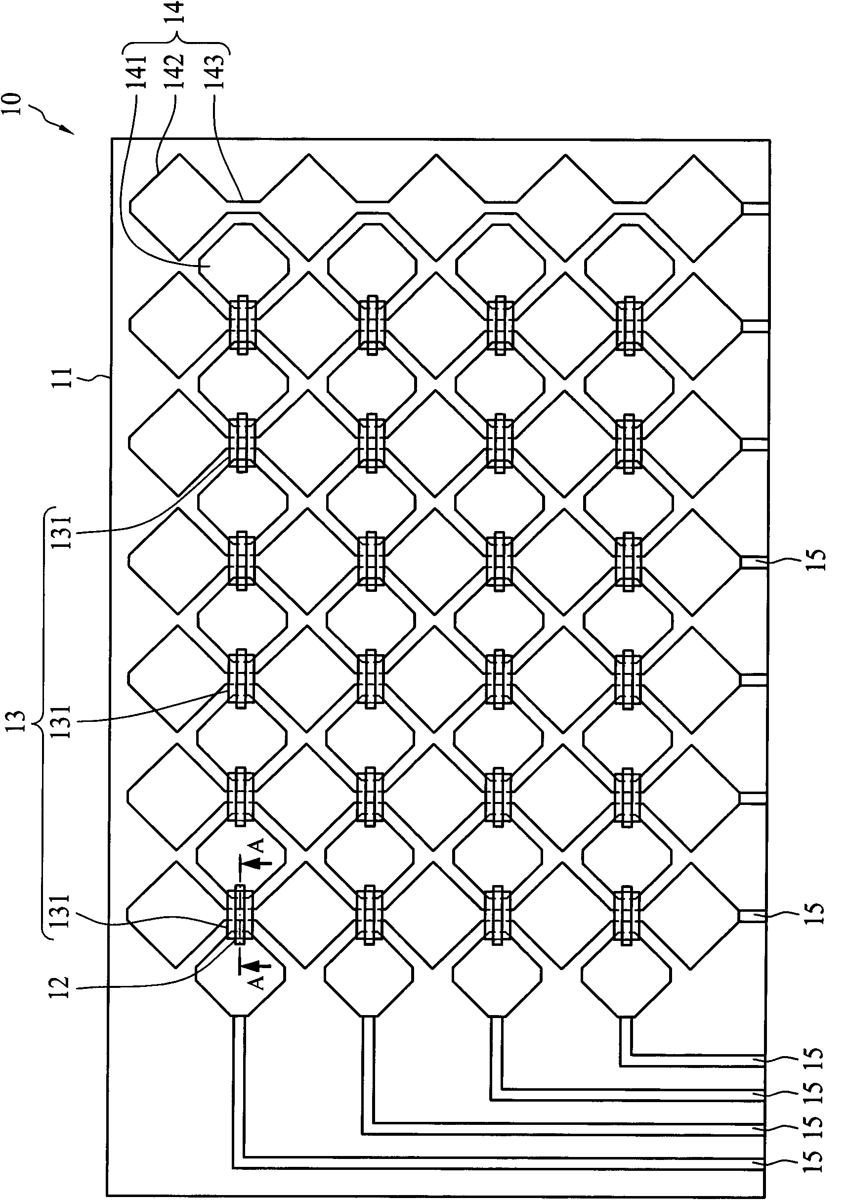
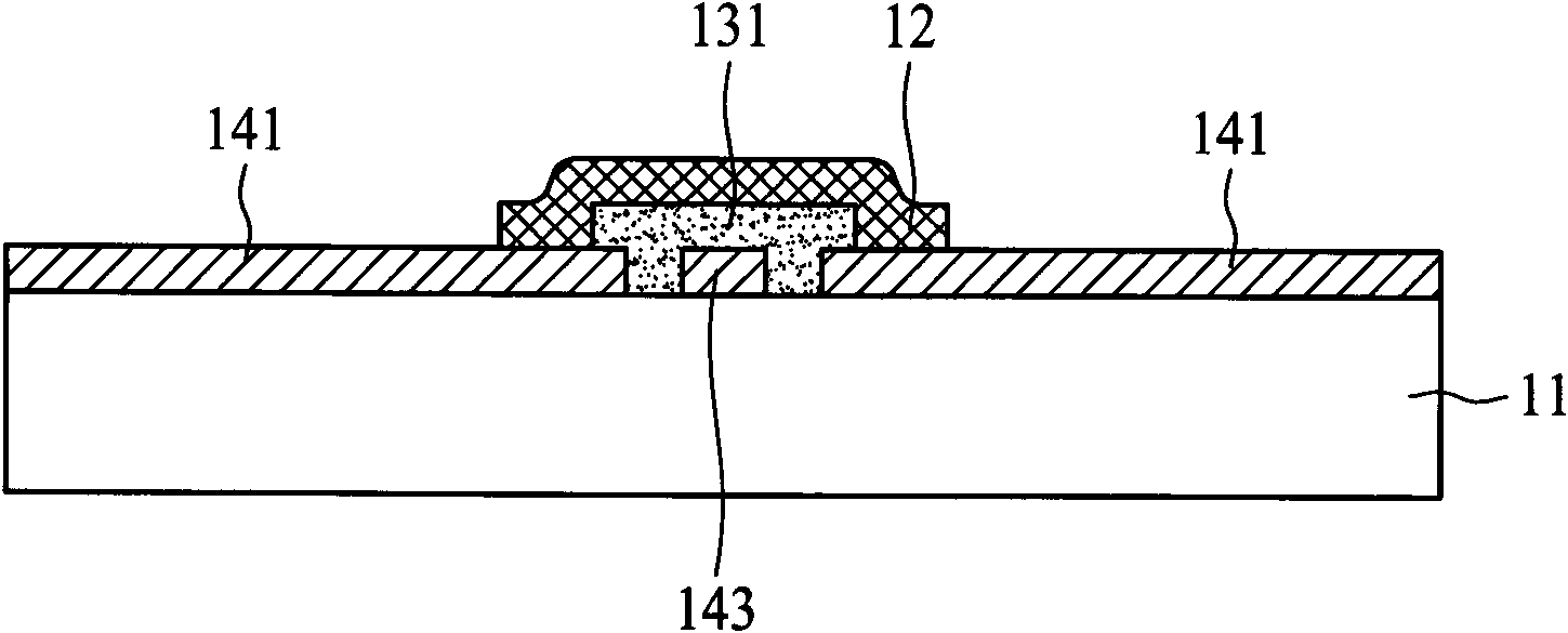
However, the lens and the transparent substrate 11 of the light-transmitting touch panel 10 are made of the same glass material, so it will not only consume materials and increase manufacturing steps, but also absorb more light from the display screen and cause the image to become dark.

Method used


Image

  • Capacitive touch panel
  • Capacitive touch panel
  • Capacitive touch panel

Examples


Embodiment Construction

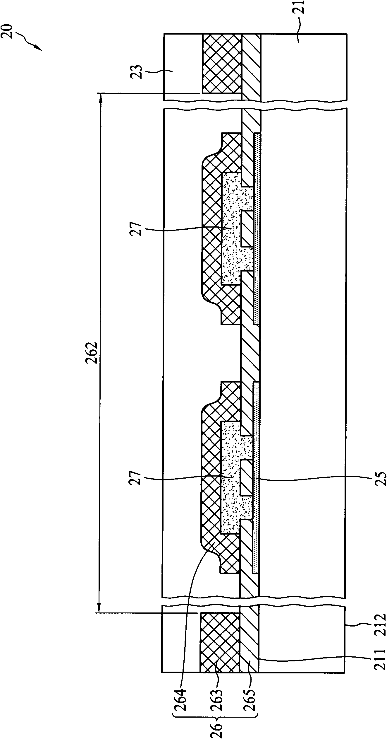
[0035] Figure 2A is a schematic cross-sectional view of the touch panel according to the first embodiment of the present invention. Such as Figure 2A As shown, a capacitive touch panel 20 includes a transparent substrate 21 , a protective layer 23 , a light shielding layer 25 , a capacitive sensing circuit element 26 and an insulating layer 27 . The capacitive sensing circuit element 26 is disposed on the first surface 211 of the transparent substrate 21 , and includes a sensing area 262 and a plurality of metal wires 263 . The sensing region 262 includes a plurality of conductive bridge lines 264 and a transparent conductive layer 265 . The plurality of metal wires 263 are located around the sensing region 262 and are electrically connected to the sensing region 262 . The light shielding layer 25 is directly disposed on the first surface 211 of the transparent substrate, that is, it is interposed between the capacitive sensing circuit element 26 and the transparent subst...


PUM


Abstract

The invention discloses a capacitive touch panel, comprising a transparent substrate, a light shielding layer and a capacitive induction circuit element, wherein the capacitive induction circuit element is arranged above one surface of the transparent substrate and comprises a sensing zone and multiple metal wires; the sensing zone comprises multiple conductive bridging lines; the multiple metal wires are arranged around the sensing zone and are electrically connected with the sensing zone; and the light shielding layer and the multiple conductive bridging lines are vertically overlapped. When a user observes and uses the capacitive touch panel, the conductive bridging lines are shielded by the light shielding layer so as to eliminate or reduce the probability that the conductive bridging lines reflect light, so that no bright spots or bright lines can be generated in the sensing zone, and the user is free of troubles in viewing a display screen and uncomfortable vision.

Description

technical field [0001] The present invention relates to a light transmission touch panel, in particular to a touch panel with a capacitive circuit. Background technique [0002] Touch panels have been widely used in fields such as household products, communication devices, and electronic information devices. Usually, touch panels are used as input interfaces of personal digital assistants (PDAs), electronic products, and game consoles. The current trend of integration of touch panels and display screens allows users to select representative icons displayed on the panel with fingers or stylus, so that personal digital assistants, electronic products and game consoles can perform favorite functions. This kind of touch panel is also applied to the public information query system, which can provide the public with an efficient operating system. [0003] A conventional touch panel includes a transparent substrate, and the transparent substrate has a surface composed of a plural...

Claims


Application Information

Patent Timeline
Patent Type & Authority Applications(China)
IPC IPC(8): G06F3/044
CPCG06F3/044G06F2203/04111G06F3/0443G06F3/0446
Inventor 黄冠铭邹忠哲李贤斌李文彩黄文宣
Owner RITFAST CORP
Learn More