


Quick Research
Generate reliable direction feasibility study reports for your R&D in just a few steps.

Technical Q&A
Discover and master advanced knowledge NOW. Basics, ideas, possibilities, all at once.

Find Solutions
As an expert in R&D theories, this can generate solutions to your technical problems instantly.

Evaluate Feasibility
Analyze your overall solution with one click, know your potential R&D risks in advance.

Monitor Landscape
Get weekly tech updates, stay abreast of the latest tech innovations and key insights.
Optical disc and optical disc apparatus
An optical disc, optical disc recording technology, applied in the direction of optical recording system, optical recording/reproduction, optical recording/reproduction/erasing method, etc., can solve the problems of destroying BD interchangeability, unsatisfactory, etc.
- Summary
- Abstract
- Description
- Claims
- Application Information
AI Technical Summary
Problems solved by technology
Method used
Image

Examples
Embodiment 1
[0062] A method of recording recording strategy information on an optical disc as an embodiment of the present invention will be described with reference to the drawings.
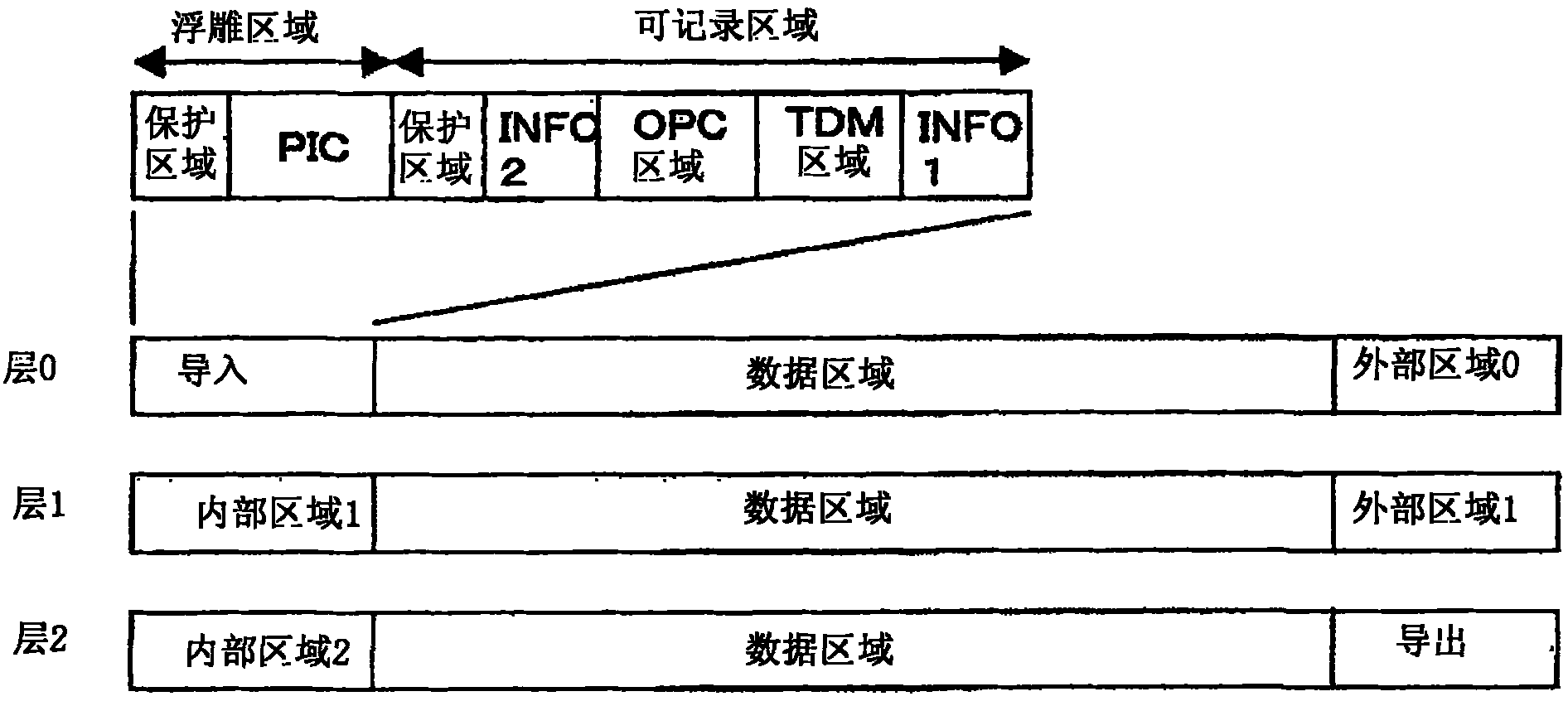
[0063] figure 2 This is an example of the optical disc structure of this embodiment.
[0064] It has three recordable information recording layers, which are called layer 0, layer 1, and layer 2, respectively. Layer 0 and layer 2 perform recording and reproduction from the inner periphery to the outer periphery, and layer 1 performs recording and reproduction from the outer periphery to the inner periphery.
[0065] A lead-in area is set in the inner peripheral area of layer 0 as a management area, and a lead-out area is set in the outer peripheral area of layer 2 as a management area.
[0066] The lead-in area is divided into an emboss area on the inner side and a recordable area on the outer side, and the emboss area is further composed of a protection area and a PIC (permanent information and cont...
Embodiment 2
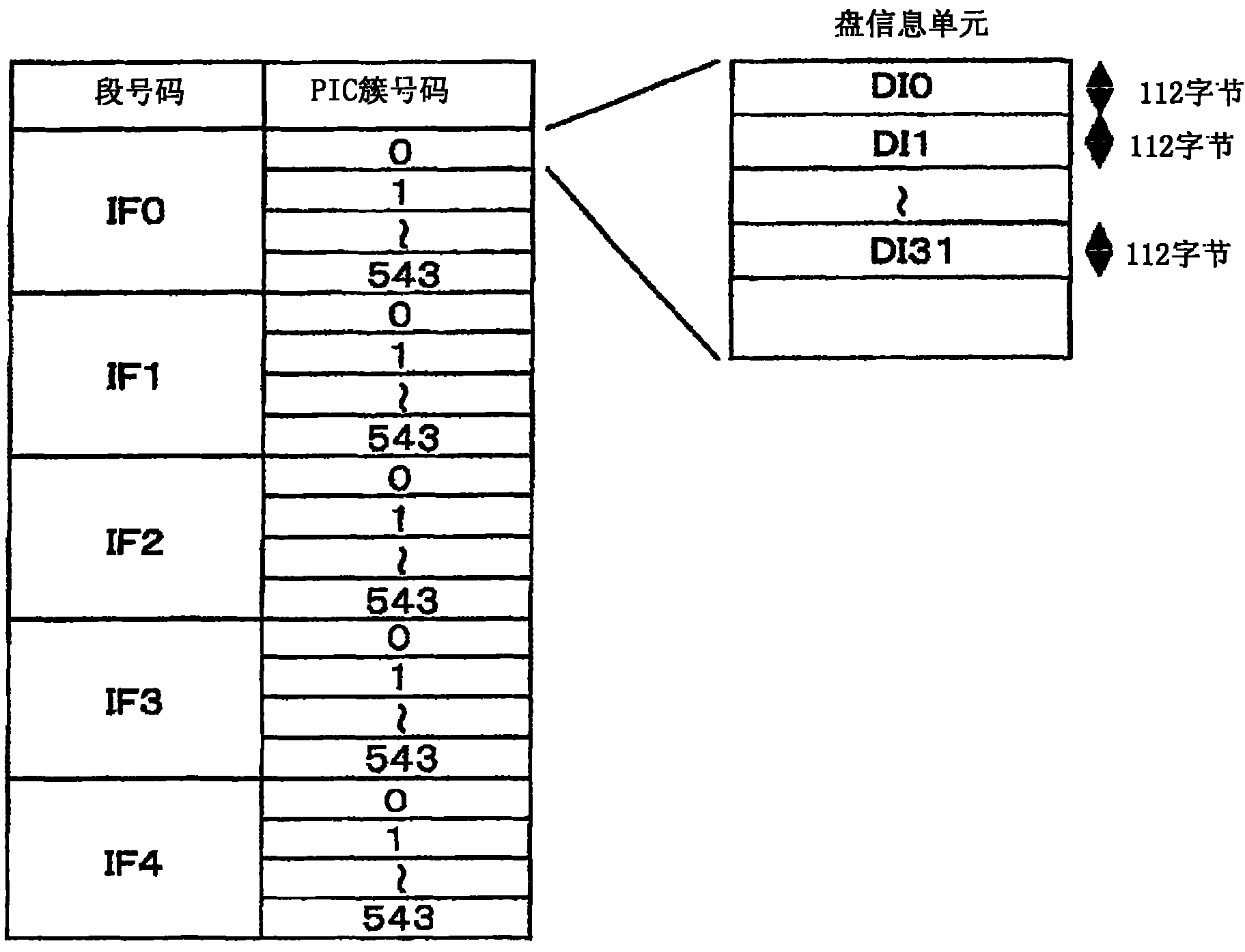
[0091] Figure 6 This is an example of the DI unit in the management area of the optical disc in this embodiment.
[0092] Figure 16 is an example of the format of the first physical disk information in Embodiment 2, Figure 17 This is an example of the format of the second physical disk information in the second embodiment, and the recording strategy type is n-1 strategy.
[0093] Different from Embodiment 1, in this embodiment, a DI unit whose connection flag is on indicates that residual disk information exists in DI units of other clusters. The connection flag of DI0 of cluster number 0 is turned on (on) for recording. Like the first embodiment, the first physical disk information is recorded in DI0, and the second physical disk information is recorded in the main body of DI32 of cluster number 1.
[0094] Since the number of DI units per cluster is 32, the maximum number of logical disk information that can be recorded in Embodiment 1 is 16, but it can be increased ...
Embodiment 3
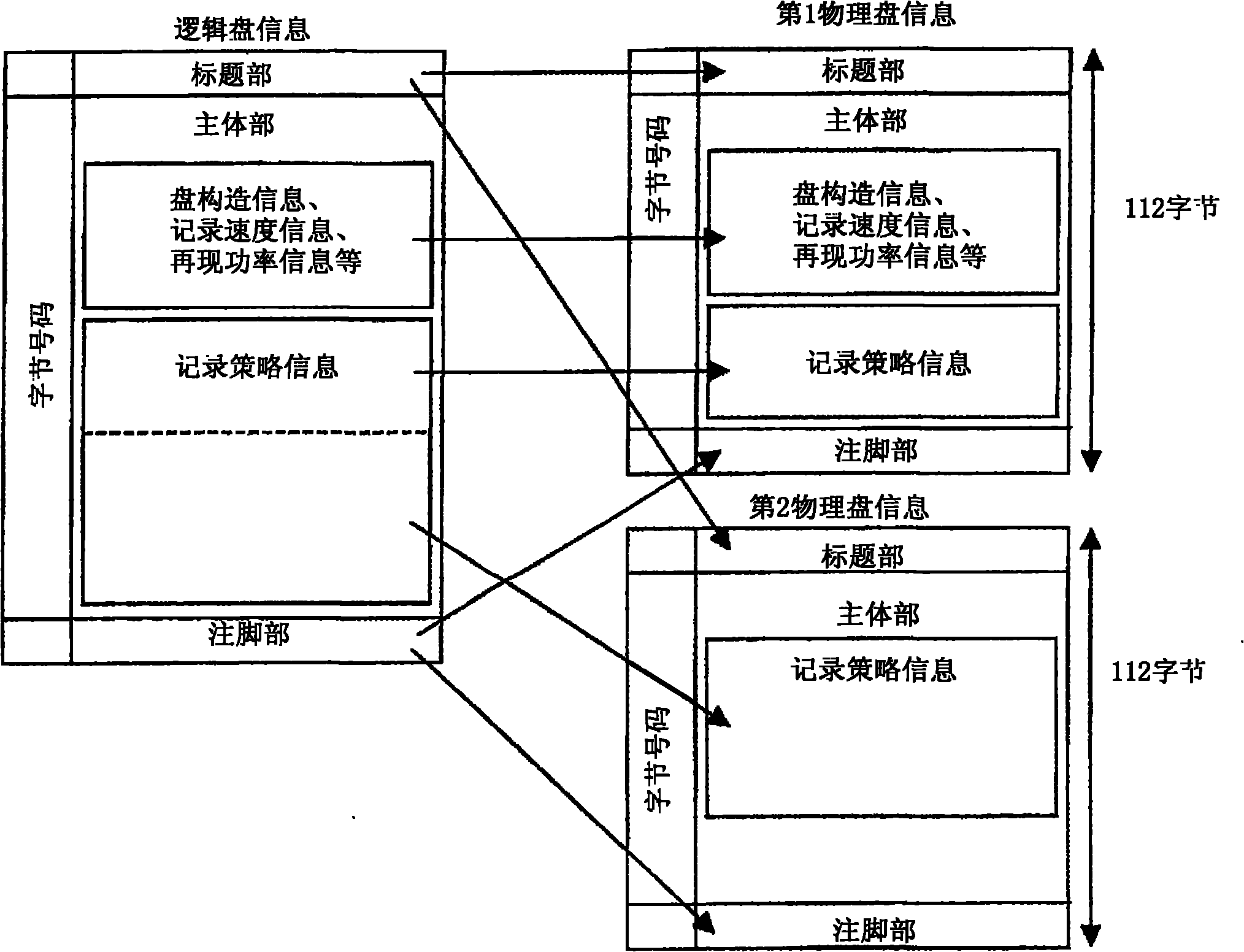
[0097] Figure 7 It is an example of the data structure of the disc information in the third embodiment, and shows the correspondence between the logical disc information and the physical disc information.
[0098] The difference from the first embodiment is the content of the recording strategy information recorded in the first and second physical disk information. In the first embodiment, the binary division was simply performed, but in the present embodiment, the classification related to the mark length or the gap length in the reference table is duplexed.
[0099] by Figure 5 Take the classification related to the pre-gap length of the parameter of the start pulse position (dTtop) of the recording strategy as an example to illustrate the duplication of classification.
[0100] First, as the first classification, it is classified into 2T space (space) and 3T space or more. About 3T clearance above, Figure 5 There are three parameters above 3T, 4T, and 5T, and among t...
PUM
 Abstract
Description
Claims
Application Information
 - R&D Engineer
- R&D Manager
- IP Professional
- Industry Leading Data Capabilities
- Powerful AI technology
- Patent DNA Extraction
Browse by: Latest US Patents, China's latest patents, Technical Efficacy Thesaurus, Application Domain, Technology Topic, Popular Technical Reports.
© 2024 PatSnap. All rights reserved.Legal|Privacy policy|Modern Slavery Act Transparency Statement|Sitemap|About US| Contact US: help@patsnap.com