Antenna structure

A technology of antenna structure and grounding wire, which is applied in the direction of antenna, antenna support/mounting device, electrical components, etc., can solve the problem of insufficient radiation area of ​​mobile phone antenna, achieve the effect of reducing the number of probes, reducing production costs, and simple design

Inactive Publication Date: 2011-03-23
ACER INC
View PDF3 Cites 7 Cited by
  • Summary
  • Abstract
  • Description
  • Claims
  • Application Information

AI Technical Summary

Problems solved by technology

[0006] In view of the above-mentioned problems in the prior art, one of the purposes of the present invention i

Method used


Image

  • Antenna structure
  • Antenna structure
  • Antenna structure

Examples


Example Embodiment

[0033] Hereinafter, the antenna structure according to the preferred embodiment of the present invention will be described with reference to related drawings. For ease of understanding, the same elements in the following embodiments are described with the same symbols.
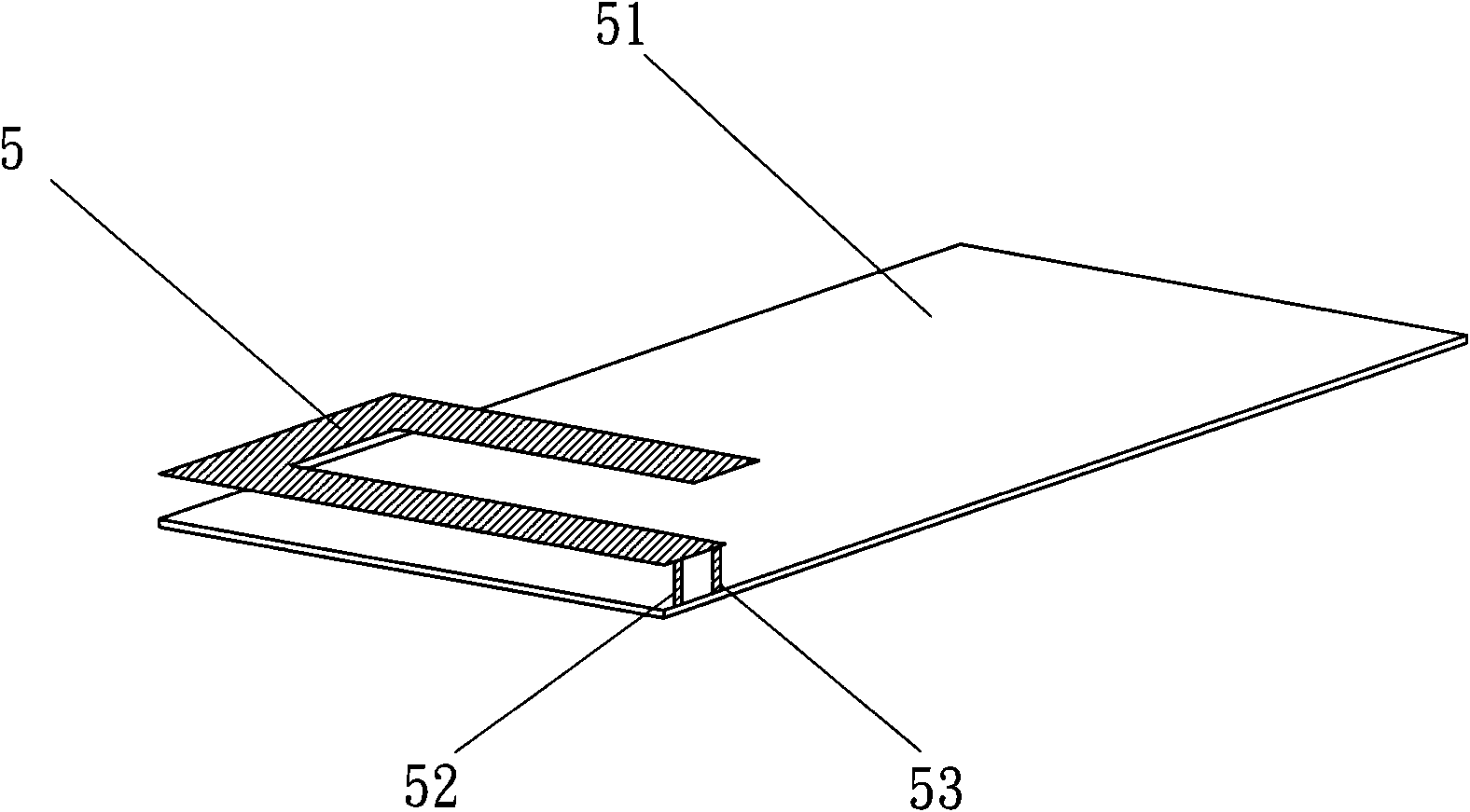
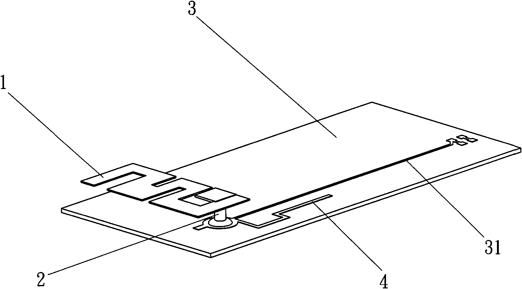
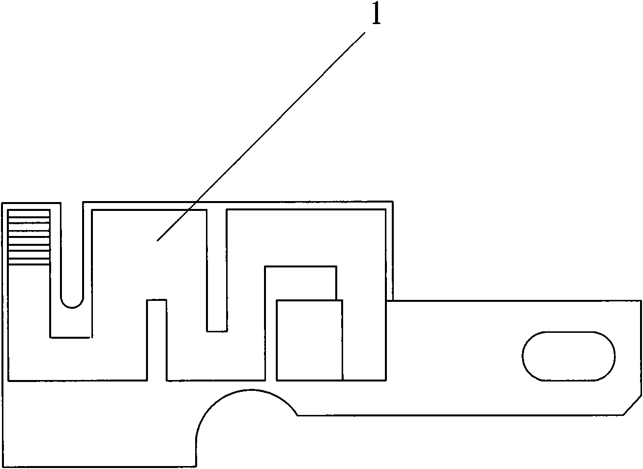
[0034] Please refer to figure 2 with image 3 , figure 2 Is a perspective view of a preferred embodiment of the antenna structure of the present invention, image 3 This is a partial enlarged view of the antenna of the antenna structure of the present invention. The antenna structure of the present invention at least includes a radiating element 1, a feeding needle 2 and a substrate 3. The plane area of ​​the radiating element 1 can determine the lowest frequency of the antenna, and the thickness of the radiating element 1 can determine the resonant frequency and bandwidth of the antenna. The substrate 3 includes a microstrip line 31 and a ground line 4, and the microstrip line 31 can be electrically connected ...


PUM


Abstract

The invention discloses an antenna structure, at least comprising a radiation member, a feed-in needle and a substrate, wherein the substrate can be a printed circuit board. One end of the feed-in needle can be connected to the radiation member and the other end thereof is electrically connected with a microstrip line and an earth wire on the substrate. Owing to only one feed-in needle in the antenna structure, the design of the radiation member can be further improved to achieve that the feed-in needle is orthogonal to the earth wire. On one hand, available space of antenna can be increased to avoid internal metal elements and raise antenna efficiency, on the other hand, such a modification can also vary the field form of antenna radiation.

Description

technical field [0001] The present invention relates to an antenna structure, in particular to an antenna structure design which reduces the overall volume of the antenna. Background technique [0002] Currently, with the increasing demand for wireless communication and mobile information terminal devices, the technical development of wireless communication is gradually improving. Playing an important role in this is the antenna, which is the main component used to transmit and receive electromagnetic waves. In terms of product manufacturing, the overall antenna is required to be lightweight, easy to carry, low power consumption and large operating bandwidth. [0003] Generally, existing mobile phone antennas are monopole antennas and planar inverted-F antennas (Planar Inverted-F Antenna, PIFA). These two have different advantages and disadvantages respectively. The advantages of single-frequency antennas lie in larger bandwidth and higher power. The disadvantage is that ...

Claims


Application Information

Patent Timeline
IPC IPC(8): H01Q13/08H01Q1/22H01Q1/24
Inventor 陈文仁
Owner ACER INC
Why Eureka
Try Eureka