
Magnetic stirring contactor

A magnetic stirring and contactor technology, applied in chemical/physical/physical-chemical stationary reactors, etc., can solve the problem of materials entering the inner cavity and so on

Active Publication Date: 2013-04-24
CHINA PETROLEUM & CHEM CORP
View PDF1 Cites 0 Cited by
  • Summary
  • Abstract
  • Description
  • Claims
  • Application Information

AI Technical Summary

Problems solved by technology

[0004] In view of this, the purpose of the embodiments of the present invention is to provide a magnetic stirring contactor to solve a series of problems caused by the materials in the reactor entering the inner cavity

Method used


Image

  • Magnetic stirring contactor
  • Magnetic stirring contactor
  • Magnetic stirring contactor

Examples


Embodiment Construction

[0019] The following will clearly and completely describe the technical solutions in the embodiments of the present invention with reference to the accompanying drawings in the embodiments of the present invention. Obviously, the described embodiments are only some, not all, embodiments of the present invention. Based on the embodiments of the present invention, all other embodiments obtained by persons of ordinary skill in the art without creative efforts fall within the protection scope of the present invention.

[0020] The embodiment of the present invention provides a magnetic stirring contactor to solve a series of problems caused by the materials in the reaction kettle entering the inner cavity.

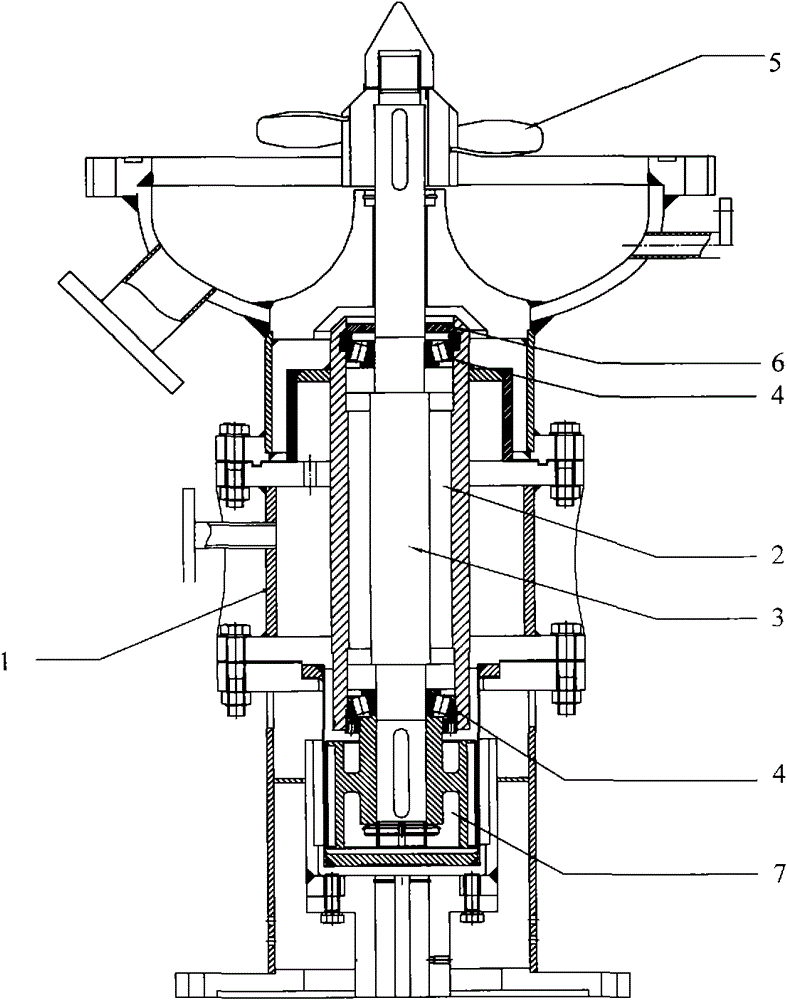
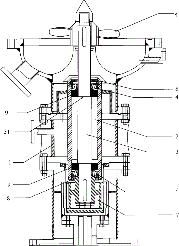
[0021] figure 2 A structure of the above-mentioned magnetic stirring contactor is shown, including an outer cavity 1 and an inner cavity 2. In the axial direction along the stirring shaft 3, the length of the inner cavity 2 is longer than that of the outer cavity 1, so the in...


PUM


Abstract

The embodiment of the invention aims to provide a magnetic stirring contactor so as to solve the problem that the wear rate of each part is accelerated caused by that materials in a reaction kettle enter the inner cavity to generate blocks and generate friction with each part during the operation of the magnetic stirring contactor, and solve the problem of corrosion of the materials on each part in the inner cavity. The magnetic stirring contactor comprises an outer cavity, the inner cavity, a stirring shaft and an impeller, wherein the inner cavity is partially arranged in the outer cavity; the stirring shaft is fixed in the inner cavity; the impeller is arranged outside the outer cavity and is connected with the stirring shaft; a seal ring is arranged on the end face, close to the impeller, of the inner cavity; and preferably, the seal ring is particularly a skeleton seal ring. The seal ring of the embodiment of the invention can prevent the materials in the reaction kettle from entering the inner cavity, so a series of problems caused by that the materials in the reaction kettle enter the inner cavity are solved.

Description

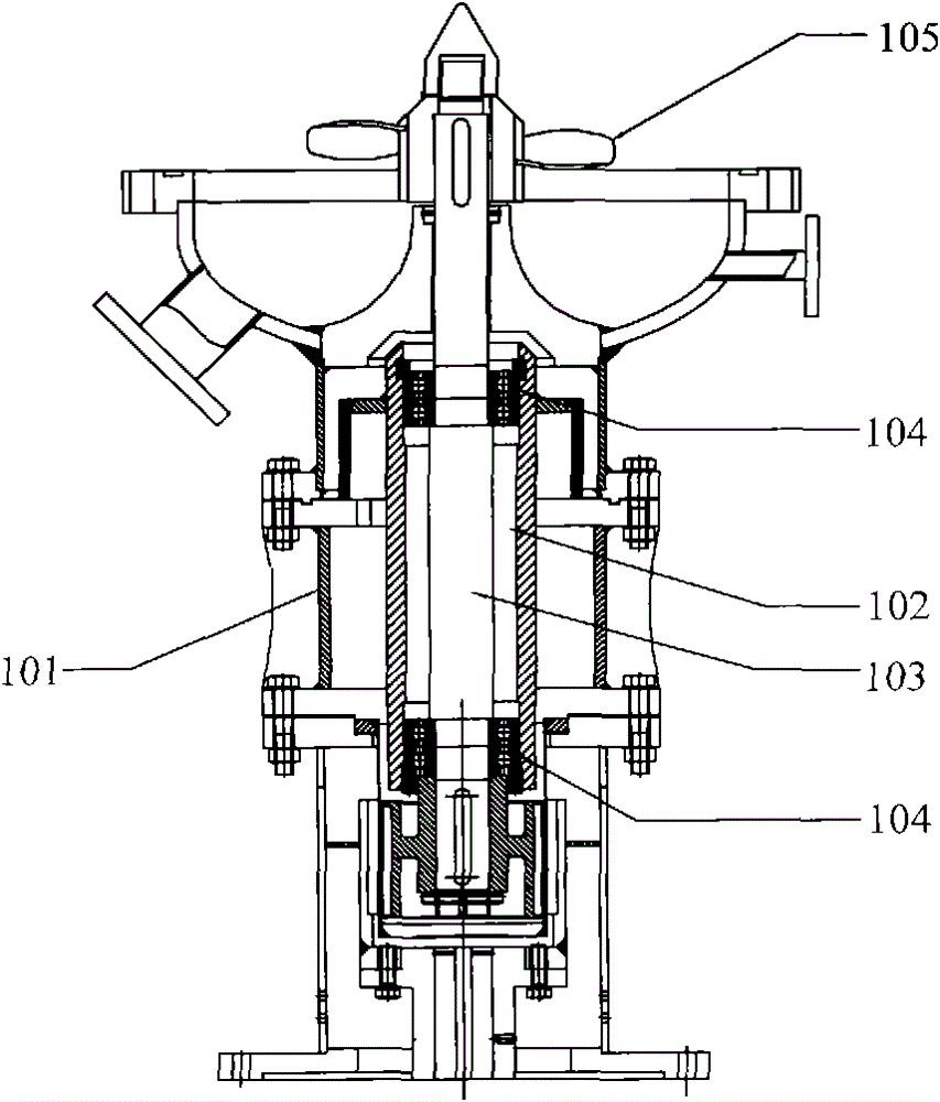
technical field [0001] The invention relates to the technical field of grease preparation, in particular to a magnetic stirring contactor. Background technique [0002] The magnetic stirring contactor is the key equipment for the production of grease. figure 1 The structure of the existing magnetic stirring contactor is shown, which mainly includes an outer cavity body 101, an inner cavity body 102, a stirring shaft 103 placed in the inner cavity body 102, and both ends of the stirring shaft 103 are respectively fixed in the inner cavity by bearings 104 In the body 102, and the impeller 105 connected with the stirring shaft 103. In the axial direction along the stirring shaft 103 , the inner cavity 102 is longer than the outer cavity 101 , so the inner cavity 102 is only partially located in the outer cavity 101 . The inner cavity 102 is filled with lubricating grease to reduce the friction between the stirring shaft 103 and other components when the stirring shaft 103 run...

Claims


Application Information

Patent Timeline
Patent Type & Authority Patents(China)
IPC IPC(8): B01J19/18
Inventor 陈晓凯杨清雄谭英明
Owner CHINA PETROLEUM & CHEM CORP
Learn More