Method for controlling rigidity of mill housing

A rolling mill stand, stiffness technology, used in metal rolling stands, metal rolling mill stands, rolling force/roll gap control, etc.

Active Publication Date: 2011-03-30
BAOSHAN IRON & STEEL CO LTD
View PDF0 Cites 15 Cited by
  • Summary
  • Abstract
  • Description
  • Claims
  • Application Information

AI Technical Summary

Problems solved by technology

[0006] By searching the technical points to be protected, and consulting non-patent documents such as relevant periodicals, magazines, manuals a

Method used


Image

  • Method for controlling rigidity of mill housing
  • Method for controlling rigidity of mill housing
  • Method for controlling rigidity of mill housing

Examples


Embodiment Construction

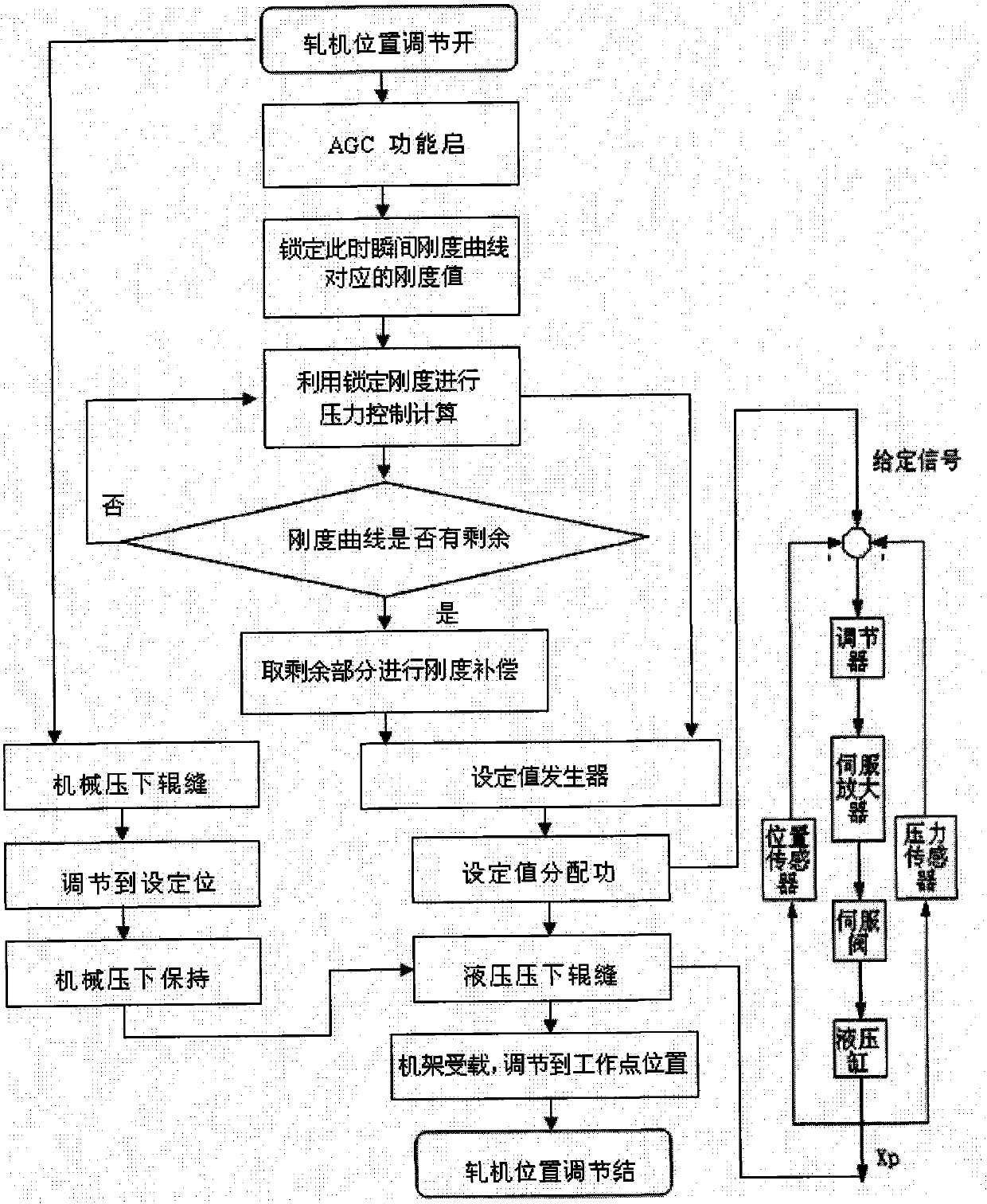
[0058] Such as image 3 The process of controlling the stiffness of the rolling mill stand is shown, and the rest of the figure refers to the deviation of the actual stiffness from the reference stiffness.

[0059] (1) Initialize rolling mill roll gap adjustment ΔS=0mm, set rolling force P=0 tons;

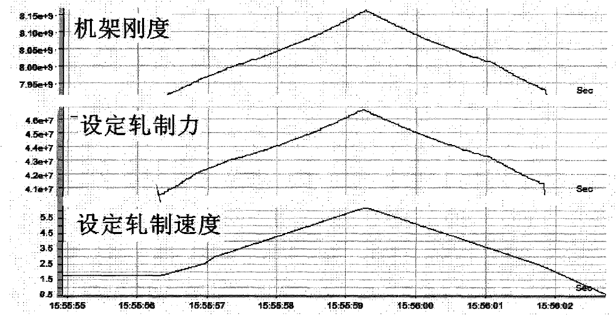
[0060] (2) Start the thickness automatic control function by the upper computer, lock the stiffness value corresponding to the stiffness curve at this moment, and use it as the reference stiffness to obtain the reference stiffness M 0 =8.74×10 9 N / m, set rolling force P=3115 tons=3115×10 4 N. Rolled piece plasticity coefficient Q=1.2×10⁹ N / m;

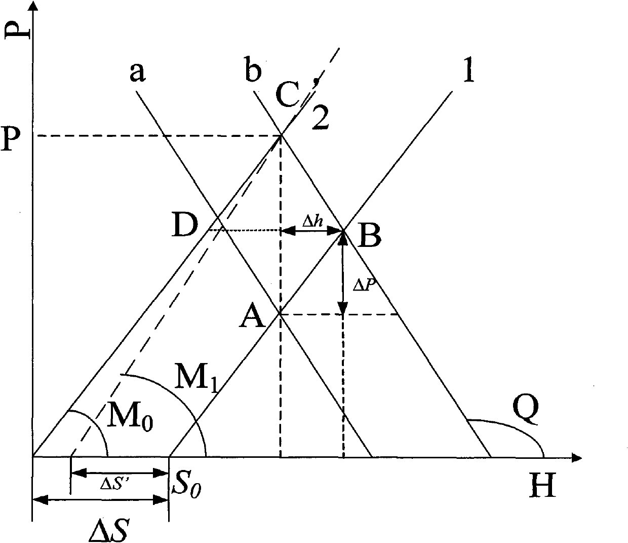
[0061] (3) if figure 2 As shown, if the frame stiffness changes at this time, by M 0 change to M 1 (that is, the dotted line in the figure), the calculated roll gap adjustment amount ΔS is not equal to the actual roll gap amount ΔS' that needs to be adjusted. In this embodiment, when the thickness automatic control function is put in...


PUM


Abstract

The invention provides a method for controlling rigidity of a mill housing, which comprises the steps of: initializing a mill roll gap regulating variable, setting a rolling force, and adopting a mechanical pressing roll gap control so that after the roll gap reaches the set position, the roll gap position set by the mechanism pressing keeps unchanged; starting thickness automatic control function, locking the momentary rigidity as reference rigidity, providing real rigidity, set rolling force, mill stand rigidity coefficient, rolled piece plasticity coefficient and roll gap set value by an upper computer; calculating the roll gap regulating variable by a formula; and regulating the roll gap by a hydraulic pressing system according to the roll gap regulating variable delta S' obtained from the calculation to a satisfactory degree and ending the regulation of the position of a mill. The invention realizes the purpose of improving the thickness control precision of rolling a wide and thick plate under the condition that the rigidity of the mill housing changes and can be popularized and applied to the improvement of various pressure AGC models for steel rolling, thereby having better popularization and application prospect.

Description

technical field [0001] The invention belongs to the metallurgical industry, in particular to a method for controlling the rigidity of a rolling mill frame. Background technique [0002] The slab thickness control system occupies a very important position in the whole steel rolling production process, and the quality of the control directly affects the quality and qualification rate of the finished steel plate. [0003] In the SIEMENS model, the frame stiffness set by the host computer is used, and the rolling data recorded in the PDA (Process Data Acquisition, referred to as PDA) is analyzed, and it is found that the frame stiffness used in the model is consistent throughout the rolling process. It changes during the manufacturing process, and its variation range is about 2 to 5%. Through the analysis, the speed of the rolling mill changes during the rolling process. When the speed of the rolling mill increases, the deformation resistance becomes larger, so the set rolling ...

Claims


Application Information

Patent Timeline
IPC IPC(8): B21B37/58B21B31/32B21B31/30
Inventor 方英汪鎏熊新华
Owner BAOSHAN IRON & STEEL CO LTD
Why Eureka
Try Eureka