
Process for producing polyurethane foam

a technology of polyurethane foam and production method, which is applied in the direction of manufacturing tools, grinding devices, other chemical processes, etc., can solve the problems of low polishing performance, inability to produce polishing layer with high thickness accuracy, and the same method, so as to achieve effective prevention of void formation, high thickness accuracy, and air trapping

Inactive Publication Date: 2012-11-20
ROHM & HAAS ELECTRONICS MATERIALS CMP HLDG INC
View PDF18 Cites 20 Cited by
  • Summary
  • Abstract
  • Description
  • Claims
  • Application Information

AI Technical Summary

Benefits of technology

The invention is a method for manufacturing a polishing pad with high thickness accuracy and substantially spherical cells. The method involves preparing a cell-dispersed urethane composition by a mechanical foaming method, continuously discharging the composition from a single discharge port to a substantially central portion in the width direction of a face material, and adjusting the thickness of the composition without applying any additional load to prevent irregularities on the surface. The method also involves curing the cell-dispersed urethane composition without applying any additional load to prevent flat cells from forming and reducing the polishing performance. The face material is fed at a rate of 0.5 to 2.5 m / minute onto an immobile plate, and the thickness of the composition is adjusted without applying any additional load to prevent air trapping and void formation. The cell-dispersed urethane composition is discharged at a rate of 0.25 to 5 L / min, with a discharge velocity of 2 to 20 m / min. The method also involves controlling the temperature of the face materials to be in the range from −20 to +20° C.

Problems solved by technology

When a pair of caterpillar belts is used, however, there is a problem in which the resulting polyurethane foam tends to have flat cells and therefore has low polishing performance.
However, this method also has the same problem as described above.
In the method of Patent Literature 3, however, it is difficult to adjust the thickness of a fluid-phase polymer composition supplied onto the undercoat layer, so that a polishing layer with high thickness accuracy cannot be produced.Patent Literature 1: JP-A 2004-169038Patent Literature 2: JP-A 2005-227392Patent Literature 3: JP-A 2003-516872

Method used

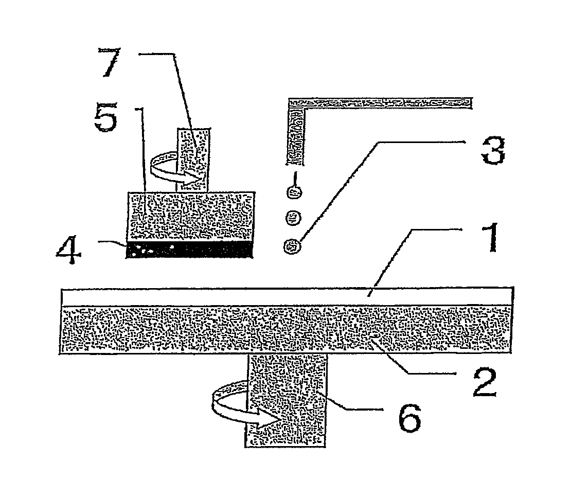
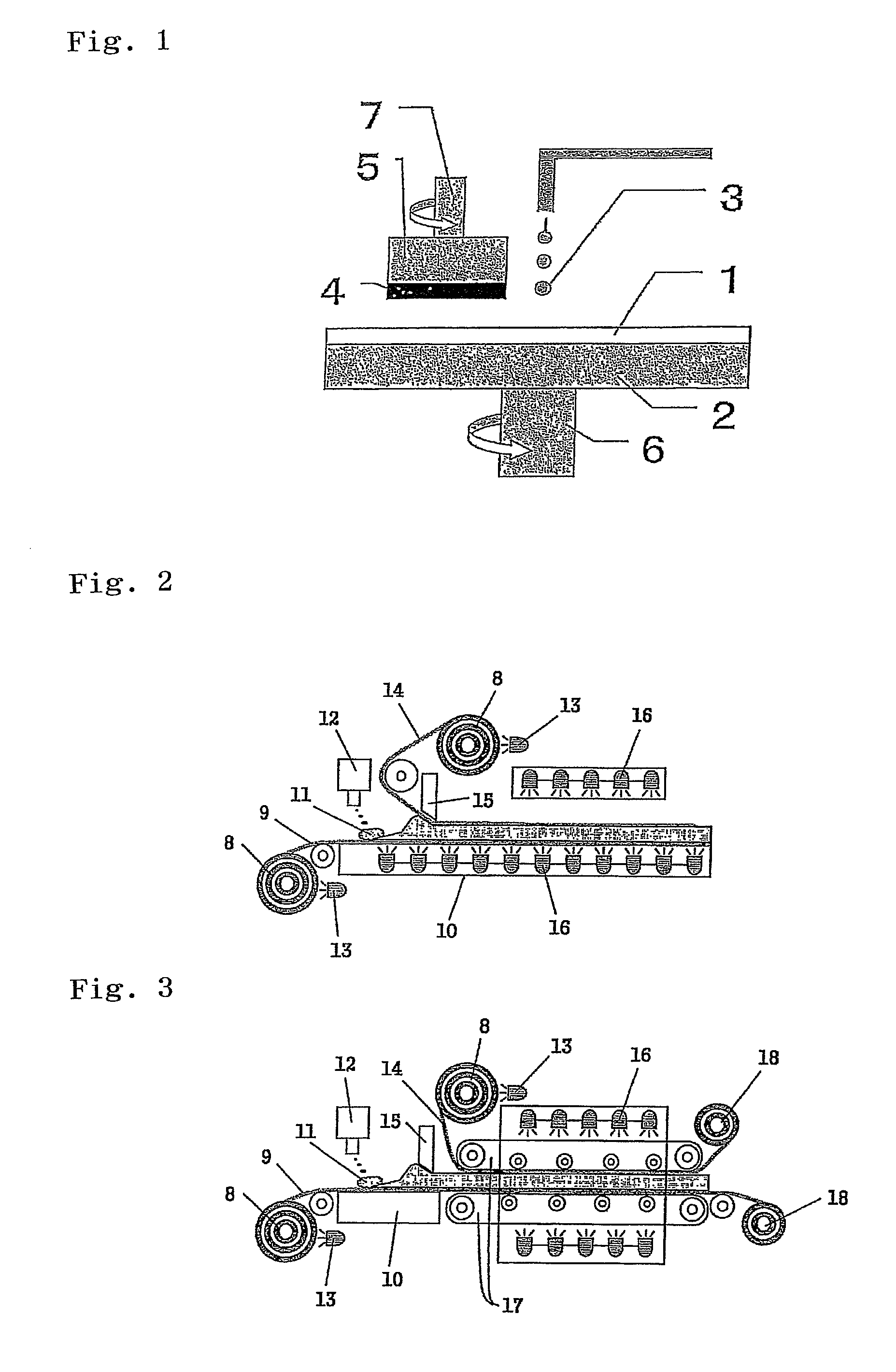
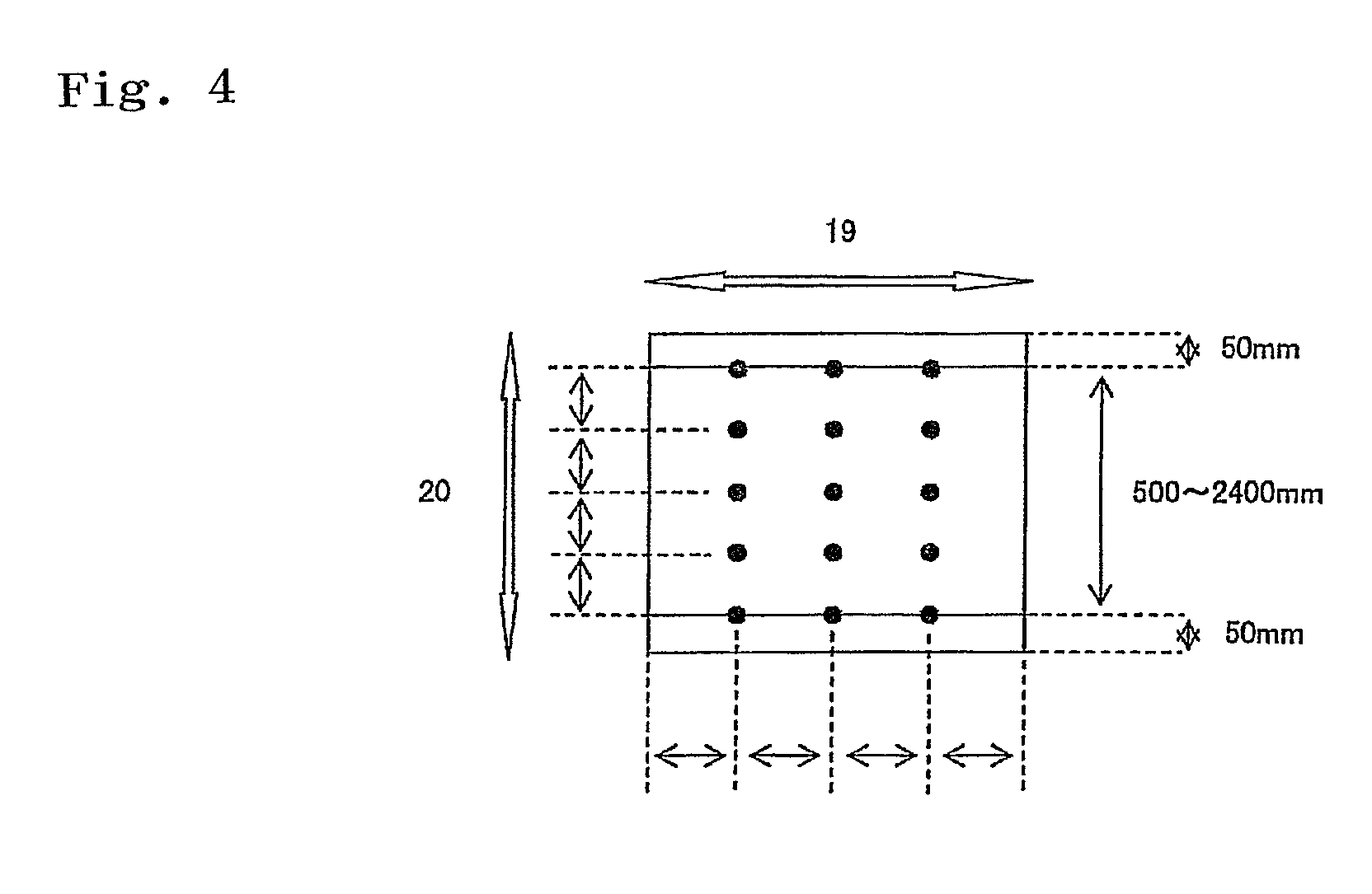

Image

  • Process for producing polyurethane foam
  • Process for producing polyurethane foam
  • Process for producing polyurethane foam

Examples


examples

[0072]Description will be given of the invention with examples, while the invention is not limited to description in the examples.

[Measurement and Evaluation Method]

[0073](Measurement of Average Cell Diameter, Evaluation of Cell Shape)

[0074]A manufactured polishing layer was sliced with a microtome cutter into measurement samples each with the thinnest possible thickness of 1 mm or less. A surface of a sample was photographed with a scanning electron microscope (manufactured by Hitachi Science System Co. with a model number of S-3500N) at a magnification of ×200. An effective circular diameter of each of all cells in an arbitrary area was measured with an image analyzing soft (manufactured by MITANI Corp. with a trade name WIN-ROOF) and an average cell diameter was calculated from the measured values. On the other hand, the cell shape was observed.

[0075](Measurement of Specific Gravity)

[0076]Determined according to JIS Z8807-1976. A manufactured polishing layer cut out in the form o...

preparation example

[0081]A mixture of 32 parts by weight of toluene diisocyanate (a mixture of 2,4-toluene diisocyanate / 2,6-toluene diisocyanate=80 / 20), 8 parts by weight of 4,4′-dicyclohexylmethane diisocyanate, 54 parts by weight of polytetramethylene glycol (1006 in number average molecular weight), and 6 parts by weight of diethylene glycol was prepared. The mixture was stirred and heated at 80° C. for 120 minutes so that an isocyanate-terminated prepolymer (2.1 meq / g in isocyanate equivalent) was prepared. One hundred parts by weight of the isocyanate-terminated prepolymer and 3 parts by weight of a silicone surfactant (SH-192 manufactured by Dow Corning Toray Silicone Co., Ltd.) were mixed to form a mixture, and the temperature of the mixture was controlled to be 60° C. In a mixing chamber, 80 parts by weight of the mixture and 20 parts by weigh of 4,4′-methylenebis(o-chloroaniline) (Iharacuamine MT manufactured by Ihara Chemical Industry Co., Ltd.) melted at 120° C. were mixed. At the same time...

example 1

[0082]While a release-treated face material A (188 μm thick, 100 cm wide) made of a PET film was thermally controlled at 50° C. by a heater and fed at a rate of 1 m / minute onto an immobile plate, the cell-dispersed urethane composition was continuously discharged from a discharge port of a mixing head to a central portion in the width direction of the face material A at a discharge rate of 1.2 L / minute and a discharge velocity of 9 m / minute (at a temperature of 62° C. during the discharge). While a release-treated face material B (188 μm thick, 100 cm wide) made of a PET film was thermally controlled at 50° C. by a heater and laminated over the composition at a feed rate of 1 m / minute, the thickness of the composition was uniformly adjusted using a doctor blade through a thickness adjusting section of 20 mm for a thickness adjusting time of 1.2 seconds. The composition was then cured by allowing it to pass through a heating oven placed at the immobile plate at 70° C. for 30 minutes ...


PUM

PropertyMeasurementUnit
temperatureaaaaaaaaaa
discharge velocityaaaaaaaaaa

Abstract

A method for manufacturing a polishing pad containing substantially spherical cells and having high thickness accuracy includes preparing a cell-dispersed urethane composition by a mechanical foaming method; continuously discharging the cell-dispersed urethane composition from a single discharge port to a substantially central portion in the width direction of a face material A, while feeding the face material A; laminating a face material B on the cell-dispersed urethane composition; then uniformly adjusting the thickness of the cell-dispersed urethane composition by thickness adjusting means; curing the cell-dispersed urethane composition with the thickness adjusted in the preceding step without applying any additional load to the composition so that a polishing sheet including a polyurethane foam is formed; and cutting the polishing sheet.

Description

REFERENCE TO RELATED APPLICATIONS[0001]This application is a national stage application under 35 USC 371 of International Application No. PCT / JP2008 / 053602, filed Feb. 29, 2008, which claims the priority of Japanese Patent Application No. 2007-081403, filed Mar. 27, 2007, the contents of both of which prior applications are incorporated herein by reference.FIELD OF THE INVENTION[0002]The present invention relates to a method for production of a polishing pad by which the planarizing processing of optical materials such as lenses, reflecting mirrors and the like, silicon wafers, glass substrates for hard disks, aluminum substrates, and materials requiring a high degree of surface planarity such as those in general metal polishing processing can be carried out stably with high polishing efficiency. The polishing pad of the present invention is used particularly preferably in a process of planarizing a silicone wafer, and a device having an oxide layer, a metal layer or the like formed...

Claims


Application Information

Patent Timeline
Patent Type & Authority Patents(United States)
IPC IPC(8): H01L21/302B24B37/20B24B37/24C08J9/30H01L21/304
CPCB24B37/24B24D3/32C08J9/30B24D18/00C08J2375/04B24D11/00H01L21/304
Inventor HIROSE, JUNJIFUKUDA, TAKESHIDOURA, MASATOSATO, AKINORINAKAMURA, KENJI
Owner ROHM & HAAS ELECTRONICS MATERIALS CMP HLDG INC
Learn More