Rough grinding tool

A technology of rough grinding and abrasive tools, applied in abrasives, manufacturing tools, metal processing equipment, etc., can solve problems such as cracking of the substrate carrying abrasives, and achieve the effect of increasing processing power and avoiding damage

Inactive Publication Date: 2011-03-30
FA AUGUST RUGGEBRERG
View PDF13 Cites 1 Cited by
  • Summary
  • Abstract
  • Description
  • Claims
  • Application Information

AI Technical Summary

Problems solved by technology

[0013] If grinding discs with coarse-grained abrasives are used for coarse grinding, as is usually the case in practice, there is a risk of cracking of the substrate carrying the abrasive
This danger is especially present when discs for abrasives made of less strong materials are used as substrates

Method used


Image

  • Rough grinding tool
  • Rough grinding tool
  • Rough grinding tool

Examples


Embodiment Construction

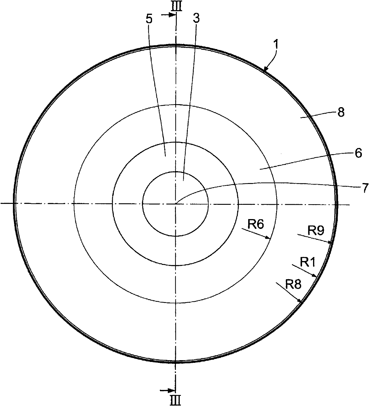
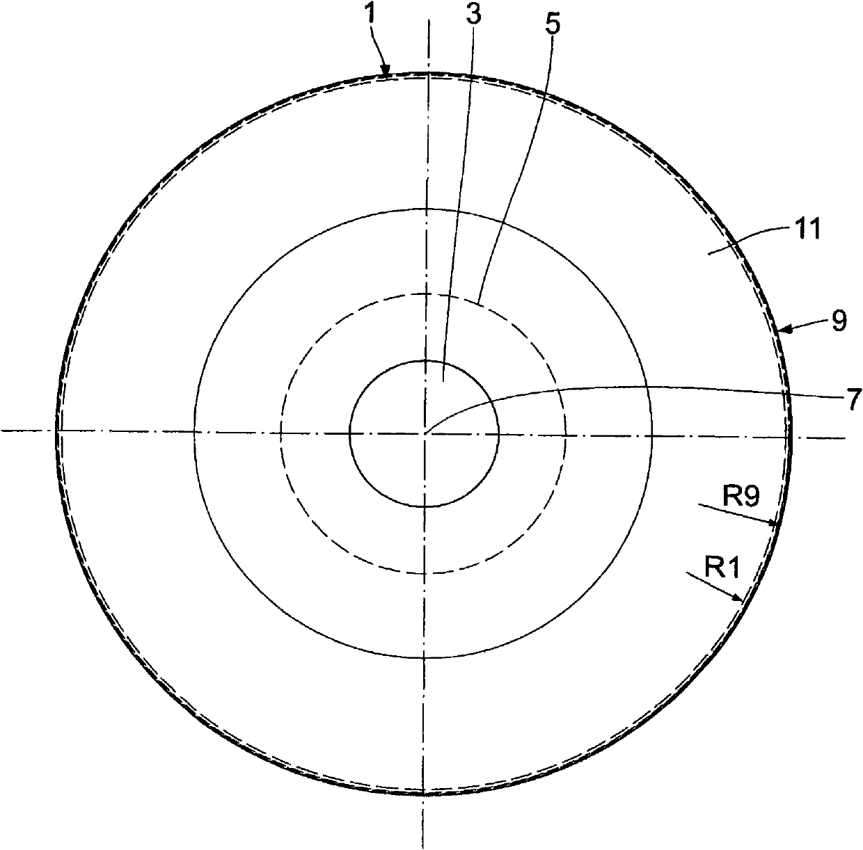
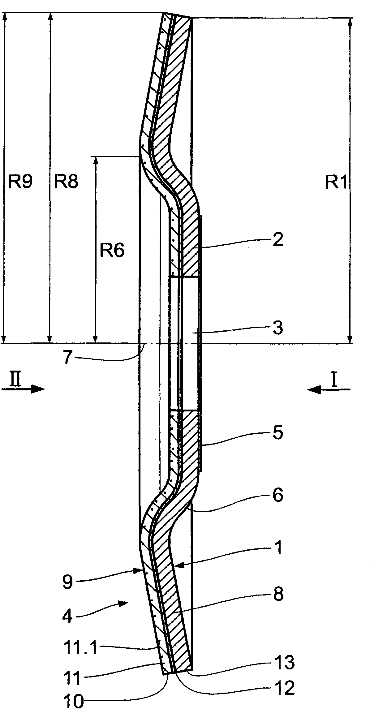
[0027] exist Figure 1 to Figure 3 The rough grinding tool shown in has a support plate 1 made of compressed glass fibers impregnated with phenolic resin in a conventional manner and has a flat, annular clamping region 2 in which A likewise circular hole 3 in the tight area is designed to receive the drive shaft of the drive. The annular clamping region 2 surrounding the bore 3 is provided with a metal ring 5 on the rear side of the carrier plate 1 facing away from the grinding side 4 . The clamping area 2 is adjoined by a curved area 6 which is also annular and rises radially with respect to the axis 7 of the bearing plate 1 towards the grinding side 4 . The annular grinding region 8 adjoins the bending region 6 and is inclined radially opposite to the bending region 6 relative to the axis 7 , in particular radially outwardly away from the grinding side 4 relative to the axis 7 . Such a construction of the support plate 1 is generally known and conventional.

[0028] The f...


PUM


Abstract

The present invention relates to a rough grinding tool, having a support plate (1) that is formed concentric to a centre longitudinal axis (7) and exhibits a centre opening for receiving a drive shaft of a drive machine; and a fiber grinding disk (9) supporting the support plate and having a fiber disk (10) with a resin-bound abrasive lining (11). The fiber grinding disk exhibits a grinding side (4) and has outer annular grinding region (8, 8', 8'') that is arranged radial to the centre longitudinal axis (7, 7'). The fiber grinding disk is glued to the support plate (1).

Description

technical field [0001] The present invention relates to a kind of rough grinding tool, and this rough grinding tool has: [0002] - support plate, the support plate [0003] - constructed concentrically with the central longitudinal axis, and [0004] - have a central hole for receiving the drive shaft of the drive unit, [0005] as well as [0006] - Fiber Grinding Disc / Fiber Grinding Wheel, the Fiber Grinding Disc [0007] - including fiber discs / wheels with a resin-bonded abrasive coating, [0008] - have an outer, annular grinding zone arranged radially with respect to the central longitudinal axis, [0009] - supported on a support plate, and [0010] - have a grinding side. Background technique [0011] Rough abrasives of this type are known in practice in large numbers. Such fiber grinding discs are designed to be flexible and are detachably attached to the support plate. Said fastening to the carrier plate takes place by means of flanges which can be screw...

Claims


Application Information

Patent Timeline
Patent Type & Authority Applications(China)
IPC IPC(8): B24D7/18
CPCB24D7/04B24D3/00
Inventor B·施图肯霍尔茨N·许茨
Owner FA AUGUST RUGGEBRERG
Why Eureka
Try Eureka