Louver in hollow glass

A louver and glass technology, applied in the field of louvers, can solve the problems of incomplete turning, hollow louver glass shading, shading coefficient and thermal insulation performance deterioration, and achieve high shading performance and thermal insulation performance

Inactive Publication Date: 2011-03-30
常熟欧泰克建筑节能科技有限公司
View PDF4 Cites 5 Cited by
  • Summary
  • Abstract
  • Description
  • Claims
  • Application Information

AI Technical Summary

Problems solved by technology

However, due to the incomplete overturning of the counterweight bottom beam 20, the shielding performance, shading coefficient and thermal insulation performance of the hollow louver glass are deteriorated.

Method used


Image

  • Louver in hollow glass
  • Louver in hollow glass
  • Louver in hollow glass

Examples


Embodiment Construction

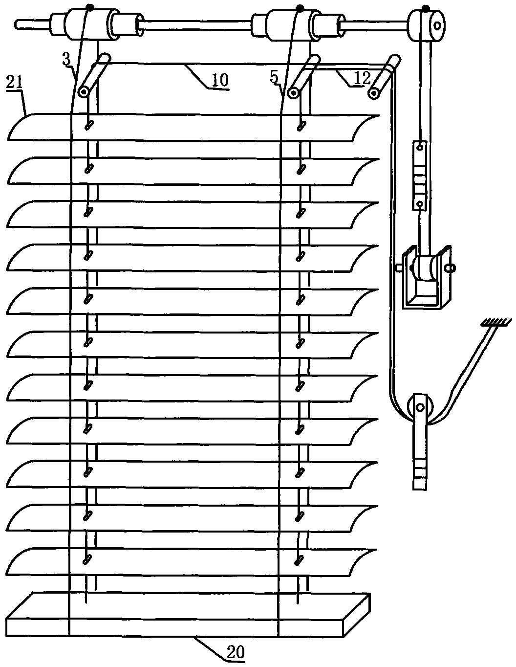
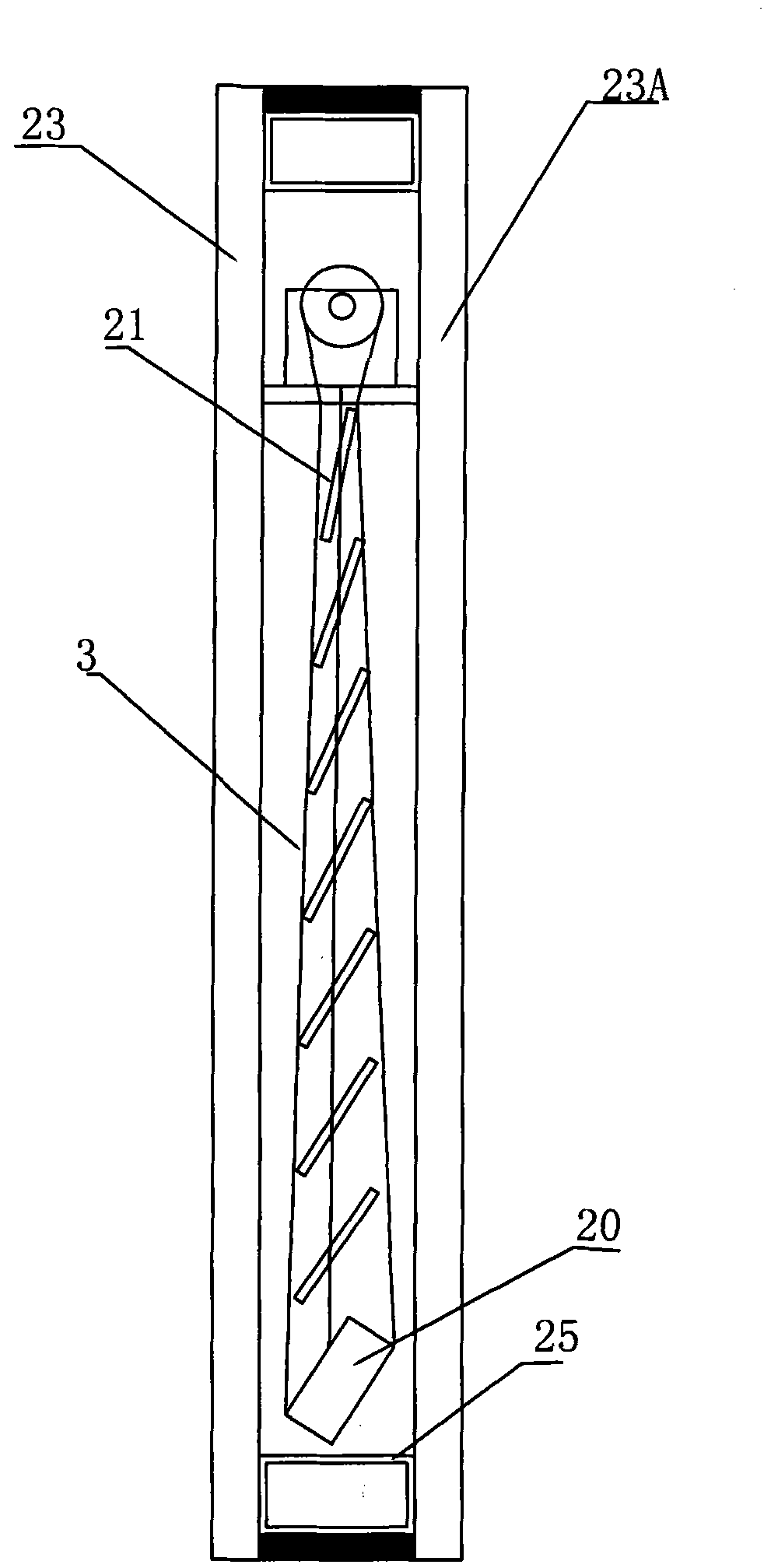
[0020] Figure 2A , Figure 2B is a structural schematic diagram of an embodiment of the present invention; Figure 2C is a schematic side view of an embodiment of the invention showing the louvers fully closed.

[0021] see Figure 2A , Figure 2B , The inside of the louver counterweight bottom beam 20 is equipped with iron wires 28 and iron wires 29 near the long sides of the left and right sides of the glass. Several magnets 16 are housed in the inside of the hollow glass lower support frame 25, only one of which has been shown in the figure. One can be set at the left and right ends of the lower support frame 25;

[0022] When the user operates the leaf turning mechanism of the shutter, the counterweight bottom beam 20 will also turn over accordingly, taking the side of the iron wire 28 as an example. The position of the iron wire 28 on one side descends and gradually approaches the lower supporting frame 25 of the insulating glass, while the position of the iron wir...


PUM


Abstract

The invention discloses a louver in hollow glass. A magnet is arranged in a supporting framework at the lower part of the hollow glass, magnetic bodies are arranged in a louver counter-weight bottom beam, and in a turnover process of the louver counter-weight bottom beam, the magnetic bodies on one descending side of the louver counter-weight bottom beam are attracted by the magnet. The turnover control of the louver is more reliable, and the shielding property, the sunshade coefficient, the heat preservation property and the total energy-saving property of hollow louver glass are improved.

Description

technical field [0001] The invention relates to a louver, in particular to a louver inside a hollow glass. Background technique [0002] For the needs of environmental protection, energy saving and comfortable life, sunshade products are widely used by people. On indoor windows, shutters (curtains) and folding blinds are more common. Insulating glass has been widely used all over the world after more than 100 years of development due to its unique heat insulation, sound insulation, anti-condensation, anti-dust pollution and other characteristics. The applicant of the present invention has previously applied for a number of patents such as ZL03238471.8 (US patent of the same family is US7124803B2), ZL200320128533.5 and ZL200420057384.2. [0003] Figure 1A , Figure 1B It is a structural schematic diagram of the utility model patent "louver in hollow glass" (patent No. ZL200420057384.2) that the designer of the present invention applied to the China Patent Office on Decemb...

Claims


Application Information

Patent Timeline
Patent Type & Authority Applications(China)
IPC IPC(8): E06B9/264E06B9/32E06B3/66
CPCE06B9/322E06B2009/3222E06B2009/2646E06B9/388E06B9/264E06B9/306
Inventor 金仁哲
Owner 常熟欧泰克建筑节能科技有限公司
Why Eureka
Try Eureka