Electric control valve

An electronic control valve and valve needle technology, applied in the direction of valve lift, valve details, valve device, etc., can solve the problems of broken magnetic rotor, stuck electronic control valve, unfavorable stability of electronic control valve, etc.

Active Publication Date: 2011-03-30
ZHEJIANG SANHUA INTELLIGENT CONTROLS CO LTD
View PDF1 Cites 15 Cited by
  • Summary
  • Abstract
  • Description
  • Claims
  • Application Information

AI Technical Summary

Problems solved by technology

[0004] In this electronic control valve, since the stop part and the magnetic rotor have an integrated structure, when the upper and lower stop sections stop the slip ring, a large stop force will be generated to act on the magnetic rotor. The impact between the lower stoppers is easy to break the magnetic rotor, thus producing fine magnetic powder, which makes the electronic control valve stuck
[0005] In addition, since the stop rod and the magnetic rotor are integrally formed, the mass distribution on the circumference of the magnetic rotor is uneven, and its center of gravity is not in the axial direction.
When the magnetic rotor rotates, it will vibrate due to the influence of eccentricity, which is not conducive to the stability of the electronic control valve, but also affects the service life of the electronic control valve, increasing the use cost of the magnetic rotor

Method used


Image

  • Electric control valve
  • Electric control valve
  • Electric control valve

Examples


Embodiment Construction

[0024] The core of the present invention is to provide an electronic control valve for controlling the flow of medium. The electronic control valve can effectively prevent the magnetic powder from falling off due to the impact of the magnetic rotor, improve the reliability and stability of the electronic control valve, and effectively improve the electronic control valve. service life.

[0025] In order to enable those skilled in the art to better understand the solution of the present invention, the present invention will be further described in detail below in conjunction with the accompanying drawings and specific embodiments.

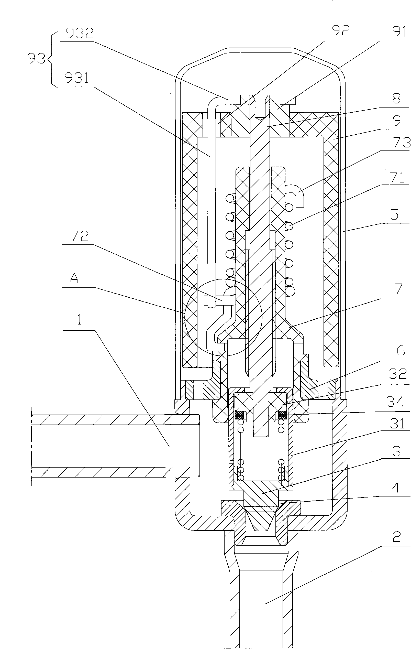
[0026] Please refer to figure 1 , figure 1 It is a structural schematic diagram of a specific embodiment of the electronic control valve provided by the present invention.

[0027] The illustrated electronic control valve includes an inlet 1 and an outlet 2, and the flow medium enters the valve body from the inlet 1; when the valve needle 3 leaves...


PUM


Abstract

The invention discloses an electric control valve. The inner cavity of a magnetic rotor (9) of the electric control valve is provided with a guidance supporting axle (7) fixedly connected with a casing (5) along the axial direction, and the guidance supporting axle (7) is screwed with a screw rod (8) through a central through hole of the guidance supporting axle; the outer wall of the guidance supporting axle (7) is provided with a spiral guidance structure (71) and a sliding component (72) sliding along the spiral guidance structure (71); the sliding component (72) slides or stops along with a stop component fixedly connected with the magnetic rotor (9); and the main body part of the stop component is arranged in the inner cavity of the magnetic rotor (9) and has a proper distance away from the side wall of the magnetic rotor (9). The electric control valve can effectively prevent the magnetic rotor (9) from magnetic powder pulloff due to impact, improve the reliability and safety of the electric control valve, and effectively prolong the service life of the electric valve.

Description

technical field [0001] The invention relates to an electronic control valve, in particular to an electronic control valve in which the main body of the stopper is arranged in the inner cavity of the magnetic rotor. Background technique [0002] In air-conditioning systems, soup dispenser systems, and air-source water heater systems, electronic control valves are usually used to adjust the flow of refrigerant and other circulating media, and the stability of their performance is closely related to the performance of the equipment using the valve. With the rapid development of my country's economic construction, the market's requirements for electronic control valves are increasing, and electronic control valves are gradually developing towards stable performance, high reliability and low cost. [0003] The Japanese patent No. JP2008032215 discloses an electronic control valve. In the electronic control valve, the magnetic rotor is arranged in the casing, and the top center of...

Claims


Application Information

Patent Timeline
Patent Type & Authority Applications(China)
IPC IPC(8): F16K1/00F16K1/32F16K31/06
Inventor 吕铭詹才意
Owner ZHEJIANG SANHUA INTELLIGENT CONTROLS CO LTD
Why Eureka
Try Eureka